Video de-interlacing method based on edge and motion detection

A motion detection and edge direction technology, applied in TV, color TV, color TV components and other directions, can solve problems such as fast and effective detection of distortion, and achieve the effect of improving viewing quality, high video quality, and simple calculation.

Active Publication Date: 2015-05-27
四川雷鸣天健新能源科技有限公司
View PDF5 Cites 0 Cited by
  • Summary
  • Abstract
  • Description
  • Claims
  • Application Information

AI Technical Summary

Problems solved by technology

[0006] The purpose of the present invention is to solve the technical problem of video deinterlacing method in the process of processing the pixel positions to be interpolated with different edge directions and edge strengths in the video and the technical problems of fast and effective detection of moving parts in the video content. Video deinterlacing method with motion detection

Method used


Image

  • Video de-interlacing method based on edge and motion detection
  • Video de-interlacing method based on edge and motion detection
  • Video de-interlacing method based on edge and motion detection

Examples


Embodiment 1

[0133] see Figure 5 , the video deinterlacing method based on edge detection of the present invention adopts the following steps to realize:

[0134] Step S100, parameter initialization: set thresholds T0=50, T1=10, T2=30, ΔT=5, and set D_cnt1=0, D_cnt2=0.

[0135]Step S200, read a field of video from the video data buffer as the current field F i , and judge the current field F i parity. If F i If it is an odd field, then continue to read the current field F i previous F i-1 and the next F i+1 After that, go to step S300; if F i is an even field, the F i The information is directly saved to the even field position corresponding to the area to be output, and returns to step S200;

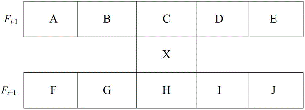
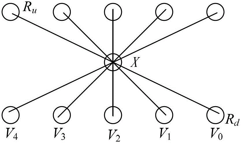
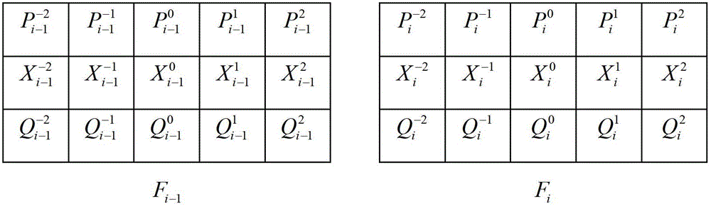
[0136] Step S300, read in the current field F in sequence i Calculate the coordinate position of each pixel to be interpolated for the unprocessed row of data; and according to the coordinate position of each pixel to be interpolated, based on formula (1), figure 1 , 2 3. Calculating th...


PUM


Abstract

The invention discloses a video de-interlacing method based on edge and motion detection and belongs to the technical field of video image processing. The video de-interlacing method includes: according to difference of corresponding pixels in a lattice between adjacent video fields, judging whether video content moves significantly or not, restoring pixels lost due to interlaced scanning by different methods based on the judgment, and selecting different candidate pixel sets for interpolation restoration on the basis of pixels to be interpolated in a lost field being subjected to multiple edge detection in front and rear fields in terms of oblique pixels and vertical pixels in the lost field. In addition, the method further includes according to the parameter results of positions of processed pixels, counting change ratio of parameters and performing dynamic self-adaptive updating to following related parameters to overcome the defect that necessary interpolation bright spots appear in an image due to inaccurate edge detection. The method is used for actual video systems related to digital video de-interlacing and is simple in calculation and high in parallelization, and videos processed by the method are high in image quality.

Description

technical field [0001] The invention belongs to the technical field of video image processing, in particular to a video deinterlacing method based on dot matrix edge and motion detection. Background technique [0002] Due to the lack of information in interlaced video, problems such as flickering between lines, jaggedness, crawling, and feathering often occur in the image during actual playback, resulting in a decline in perception. The basic function of video deinterlacing processing is to convert interlaced image signals into progressive image signals through digital processing methods, eliminate or reduce scanning lines, flickering between lines, jagged and other phenomena in interlaced video, and improve the viewing quality of video images. [0003] The key step of the video deinterlacing method is to interpolate and restore the pixels of the lost lines in a field, which is further divided into intra-field interpolation and inter-field interpolation. [0004] The intra-...

Claims


Application Information

Patent Timeline
Patent Type & Authority Patents(China)
IPC IPC(8): H04N7/01H04N5/14
Inventor 王正宁许林峰熊健伍博刘光辉李宏亮
Owner 四川雷鸣天健新能源科技有限公司
Why Eureka
Try Eureka