
Protective plug capable of checking leakage of electricity

A technology of leakage detection and voltage detection, which is applied in the direction of circuits, electrical components, coupling devices, etc., can solve problems such as induced voltage false tripping, false tripping, and current complexity, and achieve the effect of overcoming false tripping

Active Publication Date: 2014-12-10
钱加灿
View PDF5 Cites 0 Cited by
  • Summary
  • Abstract
  • Description
  • Claims
  • Application Information

AI Technical Summary

Problems solved by technology

[0004] 1. When the voltage detection transformer on the ground line is used for detection, the current on the user's ground line is very complicated, and it is easy to generate induced voltage and cause false tripping
[0005] 2. In actual use, some substations have charged zero line. This kind of electricity has no effect on electrical appliances, but it is easy to trigger the detection of the voltage detection transformer on the ground line and cause false tripping.

Method used


Image

  • Protective plug capable of checking leakage of electricity
  • Protective plug capable of checking leakage of electricity
  • Protective plug capable of checking leakage of electricity

Examples


Embodiment 1

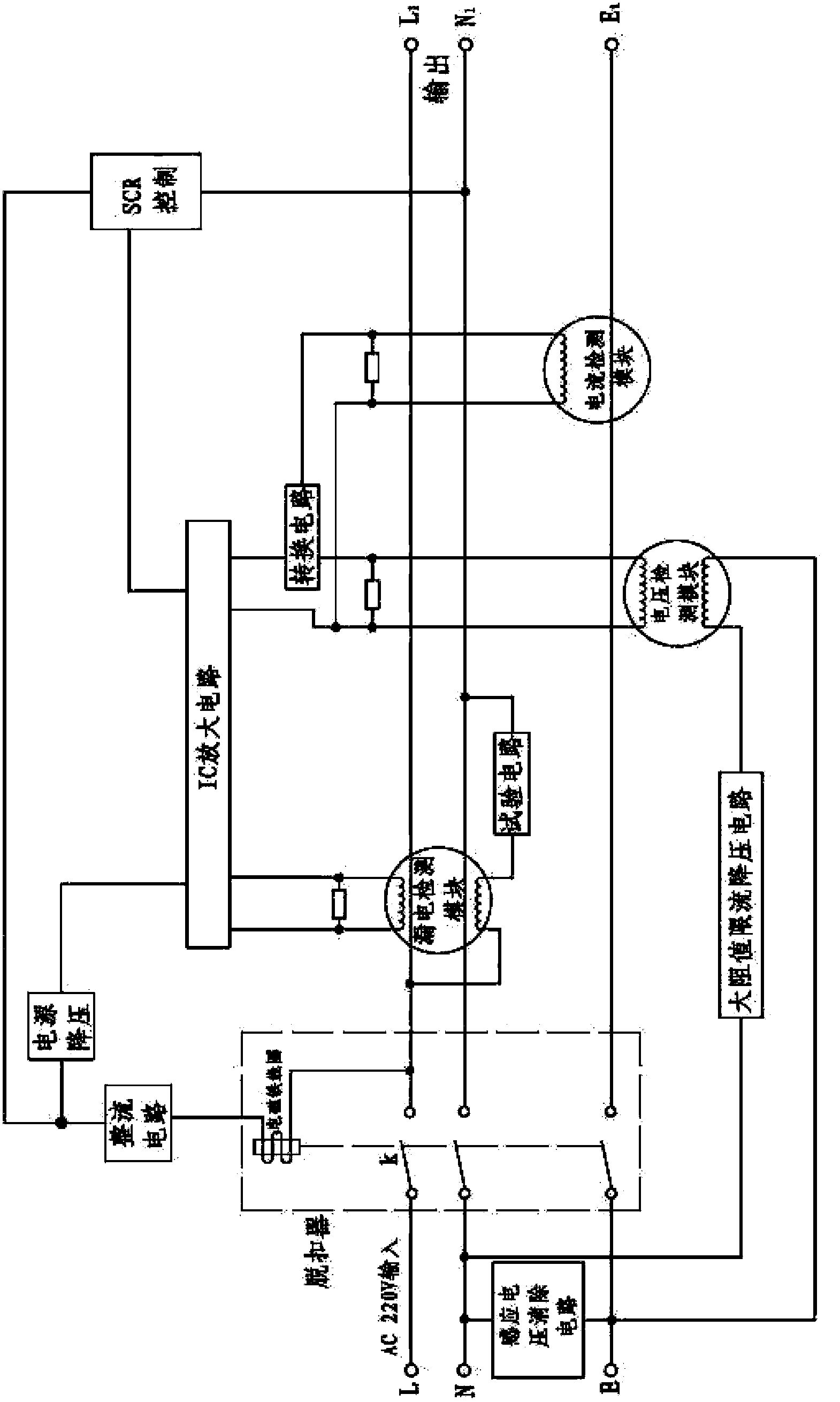
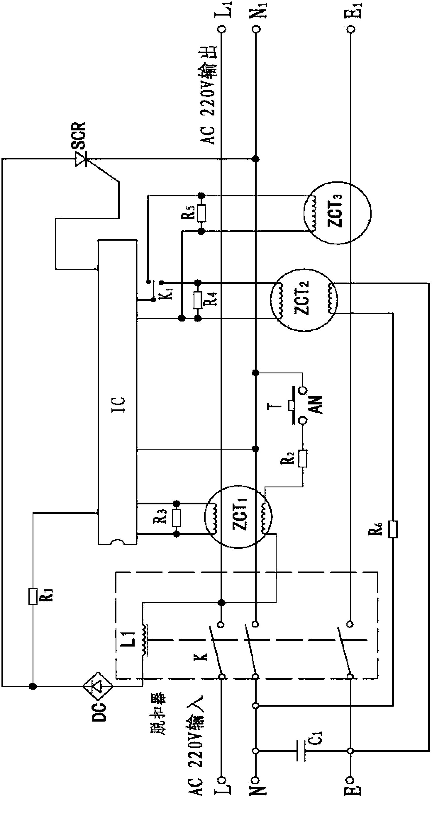
[0024] Such as figure 1 with figure 2 As shown, a leakage detection protection plug includes three poles of phase line L, neutral line N, and ground line E each with a switch K, a test circuit composed of leakage detection transformers ZCT1, R2 and AN, a release, and a rectification circuit DC, power step-down R1, thyristor SCR, voltage detection transformer ZCT2, current detection transformer ZCT3, conversion circuit K1 and a dual-input amplification circuit IC; The device ZCT3, the secondary coil of the voltage detection transformer ZCT2 and the input terminal of the amplifier circuit IC are connected, and the conversion circuit K1 is used to select the connection between the amplifier circuit IC and the voltage detection transformer ZCT2 or to select the amplifier circuit IC and the current The detection transformer ZCT3 is connected, the output end of the amplifying circuit IC is connected to the trigger pole of the thyristor touch SCR, one end of the primary coil of the...

Embodiment 2

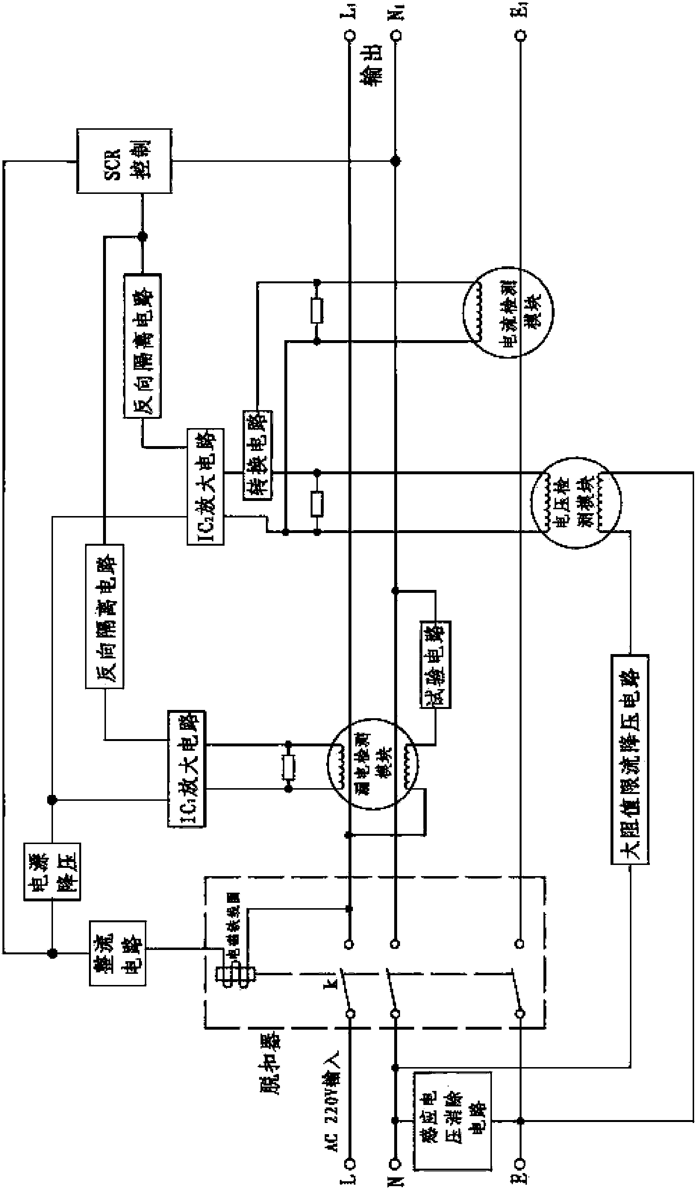
[0032] Such as image 3 with Figure 4 As shown, compared with Embodiment 1, the difference of this implementation is that two separate input amplifying circuits IC1 and IC2 are used. A diode D1 is set between the SCRs, a diode D2 is set between the output terminal of IC2 and the SCRs, the leakage detection transformer ZCT1 is connected to the amplifier circuit IC1, the voltage detection transformer ZCT2 and the current detection transformer ZCT3 are connected to IC2 through the conversion circuit K1 .

[0033] The working process is the same as that of Embodiment 1. When the neutral line N is not charged, the conversion circuit K1 conducts the amplifying circuit IC2 and the voltage detection transformer ZCT2. Once the ground line is charged, it will trigger the thyristor SCR to make the release Tripping; when the zero line is charged, it may happen that the power is turned on and the trip is mistaken. At this time, the user switches the conversion circuit K1 to the other en...


PUM


Abstract

The invention discloses a protective plug capable of checking leakage of electricity. The protective plug capable of checking leakage of electricity comprises three electrodes of a phrase line, a zero line and an earth line, an electricity leakage checking mutual inductor, a testing circuit, a release, a rectifying circuit, a power source depressurization and a controllable silicon, and the phrase line, the zero line and the earth line are respectively provided with a switch. The protective plug capable of checking leakage of electricity is further provided with a current checking mutual inductor, a voltage checking mutual inductor, a switching circuit and at least one amplifying circuit. The switching circuit is respectively connected with the current checking mutual inductor, a secondary coil of the voltage checking mutual inductor and an input end of the amplifying circuit. The switching circuit is used for choosing to connect the amplifying circuit and the voltage checking mutual inductor or to connect the amplifying circuit and the current checking mutual inductor. The output end of the amplifying circuit is connected with a controllable silicon trigger electrode, one end of the secondary coil of the voltage checking mutual inductor is connected with the ground, and the other end of the secondary coil of the voltage checking mutual inductor is connected with a big resistance value current-limiting depressurization circuit in series and then connected with the zero line. The protective plug capable of checking leakage of electricity overcomes the drawbacks that electrification of the traditional earth line induction voltage and the zero line leads to mistrip, enables functions of the protective plug capable of checking leakage of electricity to be abundant and is wide in protecting scope.

Description

technical field [0001] The invention relates to the technical field of detection plugs, in particular to a leakage detection protection plug. Background technique [0002] Existing plugs with live protection devices for ground wires, such as all-purpose leakage protection plugs, generally mean that the protection device (plug) can be disconnected when there is leakage in the phase and neutral wires, and it can also be disconnected when the ground wire is charged. It generally includes the phase, zero and ground three poles connected by the moving contact elastic sheet and the static contact, the zero-sequence current transformer passing through the phase and the neutral line, the test circuit, the amplifier circuit, the rectifier, the thyristor, the disconnector Buckle, zero-sequence current transformer passing through the ground wire, in addition to detecting whether there is leakage current between the load phase and neutral wire, it also detects whether there is leakage c...

Claims


Application Information

Patent Timeline
Patent Type & Authority Patents(China)
IPC IPC(8): H01R13/66H01R13/70
Inventor 钱加灿
Owner 钱加灿
Learn More