continuous pulse generator

A pulse generator and inverter technology, applied in the direction of pulse generation, pulse technology, electric pulse generation, etc., to achieve the effect of flexible modulation, convenient adjustment of pulse width, and simple structure

Active Publication Date: 2017-07-21
SHANGHAI INTEGRATED CIRCUIT RES & DEV CENT
View PDF4 Cites 0 Cited by
  • Summary
  • Abstract
  • Description
  • Claims
  • Application Information

AI Technical Summary

Problems solved by technology

The limitation of this method lies in the realization of high-speed logic, the control of precise phase delay and the control and improvement of pulse amplitude. At the same time, it will take some time for the price of this high-speed chip to reach the application level.

Method used


Image

  • continuous pulse generator
  • continuous pulse generator
  • continuous pulse generator

Examples


Embodiment Construction

[0030] In order to make the purpose, technical solution and advantages of the present invention clearer, the following will further describe the implementation of the present invention in detail in conjunction with the accompanying drawings. Those skilled in the art can easily understand other advantages and effects of the present invention from the contents disclosed in this specification. The present invention can also be implemented or applied through other different specific implementation modes, and various modifications or changes can be made to the details in this specification based on different viewpoints and applications without departing from the spirit of the present invention. In addition, unless otherwise specified, the "connection" involved in this specific embodiment refers to an electrical connection relationship.

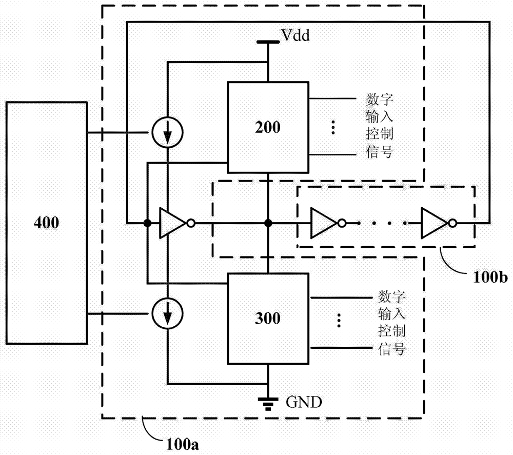
[0031] image 3 Structural block diagram of the continuous pulse generator provided by the present invention.

[0032] Such as image 3 As show...


PUM


Abstract

The present invention relates to the technical field of semiconductors, and provides a continuous pulse generator, comprising: driving a variable inverter and an inverter chain formed by an even number of inverter units in series, and the driving variable inverter includes an inverter unit , PMOS array, NMOS array. By adjusting the number of MOS transistors connected to the input end of the inverter unit in the drive variable inverter by adjusting the number of MOS transistors connected to the PMOS array and the NMOS array to adjust the inversion discrimination level, the purpose of controlling and adjusting the duty ratio of the output pulse signal is achieved. The continuous pulse generator has a simple circuit structure, is fully compatible with the existing CMOS semiconductor process, and can adjust the pulse width more flexibly and conveniently to facilitate the optimal transmission signal bandwidth, and provide pulse sequences with controllable frequencies and different pulse widths. , adjust the bandwidth of the transmission signal, get high-quality signal, make the modulation method more flexible, and widely used in the field of wireless communication.

Description

technical field [0001] The invention relates to the field of semiconductor technology, in particular to pulse generator technology. Background technique [0002] Ultra Wideband (UWB) is a wireless communication technology that uses short pulses (0.1nm~1.5ns) for transmission and has a very high bandwidth ratio (ratio of radio frequency bandwidth to center frequency). The three major advantages of good performance and not occupying new spectrum resources have emerged at the end of the 20th century and have been widely used in military and civilian fields. Compared with traditional narrowband technologies such as Bluetooth and WLAN, UWB technology has the characteristics of high transmission rate (hundreds of Mbit / s), strong anti-interference performance, low power consumption, and good confidentiality performance. It is mainly used in indoor communication, high-speed wireless LAN , radar and other fields. According to the FCC regulations of the US Federal Communications Com...

Claims


Application Information

Patent Timeline
Patent Type & Authority Patents(China)
IPC IPC(8): H03K3/017
Inventor 孙翔
Owner SHANGHAI INTEGRATED CIRCUIT RES & DEV CENT
Why Eureka
Try Eureka