A duty ratio adjustment circuit

A technology for adjusting the circuit and duty cycle, which is applied in the direction of electrical components, electric pulse generation, pulse technology, etc., can solve the problem that the duty cycle of the output signal cannot be adjusted to 50%, and achieve the effect of simple structure and wide application range

Active Publication Date: 2017-10-17
CHENGDU CORPRO TECH CO LTD
View PDF5 Cites 0 Cited by
  • Summary
  • Abstract
  • Description
  • Claims
  • Application Information

AI Technical Summary

Problems solved by technology

[0004] The existing duty ratio adjustment circuit cannot adjust the duty ratio of the output signal to 50% when the frequency division ratio is an odd number

Method used


Image

  • A duty ratio adjustment circuit
  • A duty ratio adjustment circuit
  • A duty ratio adjustment circuit

Examples


Embodiment Construction

[0024] The technical solution of the present invention will be further described in detail below in conjunction with the accompanying drawings, but the protection scope of the present invention is not limited to the following description.

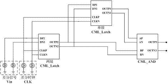
[0025] Such as figure 1 As shown, a duty cycle adjustment circuit, which includes a single-stage current-mode logic latch (single-stage CML_Latch), a two-stage current-mode logic latch (two-stage CML_Latch) and a current-mode logic AND gate (CML_AND), The differential clock CLK is respectively connected to the clock signal input terminals (CLKN and CLKP) of the single-stage current-mode logic latch (single-stage CML_Latch) and the two-stage current-mode logic latch (two-stage CML_Latch), and the differential clock CLK is input to Clock signal for the channel divider. The differential signal Vin is connected to the differential signal input terminals (DP2 and DN2) of the two-stage current mode logic latch (two-stage CML_Latch). The differen...


PUM


Abstract

The invention discloses a duty cycle corrector, which comprises a single-stage CML_Latch, a two-stage CML_Latch and CML_AND, wherein a difference clock CLK is respectively connected to the input ends of clock signals of the single-stage CML_Latch and the two-stage CML_Latch, a differential signal Vin is connected to the input end of a differential signal of the two-stage CML_Latch, the output end of the differential signal of the two-stage CML_Latch is connected to the input end of a differential signal of the single-stage CML_Latch, a first input of the CML_AND is connected to the output end of the differential signal of the single-stage CML_Latch, and a second input of the CML_AND is connected to the output end of the differential signal of the two-stage CML_Latch. According to the duty cycle corrector, adjustment of a duty ratio can be implemented through the single-stage CML_Latch, the two-stage CML_Latch and the CML_AND, and the structure is simple; when the number of high level cycles is one more than the number of low level cycles, firstly, the output is subjected to lag input for a half of clock cycle through the single-stage CML_Latch, and then the input and the output of the single-stage CML_Latch pass through the CML_AND to change the half cycle of the high level is to the low level, so that the signal without 50% of duty ratio is adjusted to the signal with 50% of duty ratio, adjustment of 50% of duty ratio is implemented when a frequency dividing ratio is an odd number, and the application range is wide.

Description

technical field [0001] The invention relates to a channel frequency divider circuit of a clock distributor, in particular to a duty ratio adjustment circuit. Background technique [0002] With the improvement of the scientific and technological content of modern warfare, the amount of information transmission and processing has increased geometrically, and more and more high-speed processing digital circuits have put forward higher and higher requirements for the performance of the clock source. Among them, the clock distributor has been widely researched and applied for its advantages of low jitter, flexible configuration, high reliability, low power consumption, and easy integration. Modern high-speed digital circuits, high-speed AD / DA sampling, digital DDS, digital microprocessors and RF circuit technology demand for clock signals, so that clock distributor technology develops rapidly and is widely used, becoming a dazzling star in clock source technology . [0003] The...

Claims


Application Information

Patent Timeline
Patent Type & Authority Patents(China)
IPC IPC(8): H03K3/017
CPCH03K3/017
Inventor 赵鹏
Owner CHENGDU CORPRO TECH CO LTD
Why Eureka
Try Eureka