Laser cladding device with adjustable duty ratio

A technology of laser cladding and duty cycle, which is applied in coating, additive manufacturing, additive processing, etc., can solve the problems of insufficient performance of formed parts, poor stability of forming process, and affecting the quality of cladding and forming, etc.

Pending Publication Date: 2022-06-24
SUZHOU UNIV
View PDF0 Cites 0 Cited by
  • Summary
  • Abstract
  • Description
  • Claims
  • Application Information

AI Technical Summary

Problems solved by technology

According to a large number of experiments, it is known that when the duty ratio is between 0.5-1, it will cause adverse effects such as excessive concentration of energy distribution, resulting in poor stability of the forming process and insufficient performance of the formed part. Therefore, this application mainly studies the control duty ratio of 0-0.5. Happening
The current conventional method of changing the laser duty cycle is to obtain different duty cycle values ​​by changing the defocus amount. The defocus amount refers to the distance between the actual cladding forming plane and the plane where the optical convergence point of the ring beam is located during the laser cladding process. However, the change of defocus will cause the change of laser energy density and the change of cladding single track width (melting width), which will affect the quality of cladding forming

Method used


Image

  • Laser cladding device with adjustable duty ratio
  • Laser cladding device with adjustable duty ratio
  • Laser cladding device with adjustable duty ratio

Examples


Embodiment Construction

[0028] The technical solutions in the embodiments of the present application will be clearly and completely described below with reference to the drawings in the embodiments of the present application. Obviously, the described embodiments are only a part of the embodiments of the present application, but not all of the embodiments. Based on the embodiments in the present application, all other embodiments obtained by those of ordinary skill in the art without creative efforts shall fall within the protection scope of the present application.

[0029] In order to make those skilled in the art better understand the solution of the present application, the present application will be further described in detail below with reference to the accompanying drawings and specific embodiments.

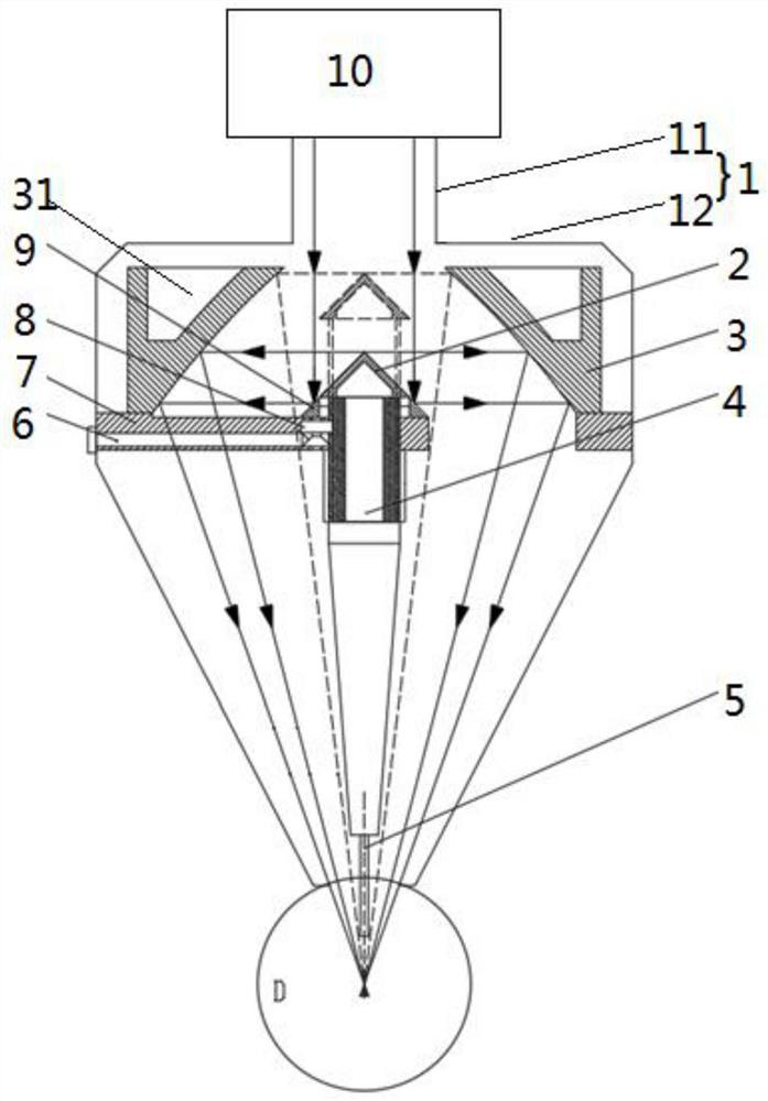
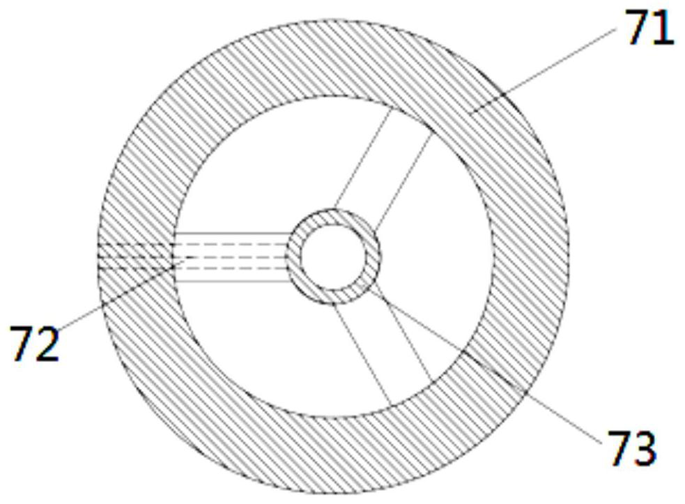
[0030] Please refer to Figure 1 to Figure 4 , figure 1 A schematic diagram of the laser cladding device with adjustable duty cycle provided by the embodiment of the present application, figur...


PUM


Abstract

The invention discloses a laser cladding device with an adjustable duty ratio. The laser cladding device comprises a lens base, a parabolic focusing lens, a fixed cone lens, a movable cone lens and a powder nozzle. The fixed cone mirror and the parabolic focusing mirror are both of an annular structure, and the reflecting surfaces of the movable cone mirror and the fixed cone mirror are both arranged opposite to the reflecting focusing surface of the parabolic focusing mirror, so that an incident light beam in the middle axis direction of the parabolic focusing mirror is reflected to the reflecting focusing surface in the circumferential direction and is reflected and focused by the reflecting focusing surface; the lens base comprises a first annular fixing part arranged on the outer periphery, a second annular fixing part arranged on the inner periphery and a rib plate connected with the first annular fixing part and the second annular fixing part. The parabolic focus lens is fixed to the first annular fixing part, the fixed cone lens is fixed to the second annular fixing part, the movable cone lens further comprises a movement adjusting part which is arranged on the second annular fixing part in a penetrating mode and drives the movable cone lens to move in the middle axis direction of the parabolic focus lens, the movable cone lens is fixed to the top end of the movement adjusting part, and the powder nozzle is fixed to the bottom end of the movement adjusting part.

Description

technical field [0001] The present application relates to the field of laser additive manufacturing, in particular to a laser cladding device with adjustable duty cycle. Background technique [0002] As an advanced surface coating preparation and additive manufacturing technology, laser cladding has achieved rapid development in recent years. [0003] This technology uses a high-energy laser beam as a processing heat source to form a small molten pool on the surface of the metal substrate, and quickly melts the material fed into the molten pool. A metallurgically bonded cladding layer or a three-dimensional part with properties comparable to as-forged components. [0004] At present, the laser cladding forming technology can be divided into two types according to the positional relationship between the laser and the powder. The coaxial powder feeding in the light uses a ring laser beam as the heating source, and the laser energy presents an M-shaped distribution, which is ...

Claims


Application Information

Patent Timeline
IPC IPC(8): C23C24/10B22F12/41B22F12/53B22F10/25B33Y30/00
CPCC23C24/10B22F12/41B22F12/53B22F10/25B33Y30/00
Inventor 李加强金磊朱刚贤石世宏
Owner SUZHOU UNIV
Why Eureka
Try Eureka