Duty ratio adjusting device and method of resonance system

A technology of resonant system and adjustment device, applied in the direction of pulse generation, electrical components, generation of electrical pulses, etc., can solve the problems of clock signal waveform distortion, voltage deviation, virtual point voltage deviation, etc., to achieve the effect of ensuring integrity

Pending Publication Date: 2019-12-20
苏州芯算力智能科技有限公司
View PDF0 Cites 0 Cited by
  • Summary
  • Abstract
  • Description
  • Claims
  • Application Information

AI Technical Summary

Problems solved by technology

[0004] However, due to the existence of parasitic capacitance and resistance, the upper and lower driving capabilities of the clock driver are not equal, resulting in the duty cycle of the clock signal in the LC resonant clock (the ratio of the high or low level of the signal in one cycle; in this case, the correct duty cycle The ratio is 50%) deviation, and the duty cycle deviation causes the voltage of the virtual point to deviate from 1 / 2VDD, and the reaction of the voltage of the virtual point to deviate from 1 / 2VDD will cause the waveform distortion of the clock signal in the LC resonant clock
like Figure 1a In, the virtual point voltage deviation, resulting in Figure 1b Distorted clock signal waveform in
[0005] In order to solve the problem of distortion of the clock signal waveform caused by the above-mentioned duty cycle and the deviation of the virtual point voltage, it is necessary to provide a technology for correcting and adjusting the duty cycle of the resonant clock

Method used


Image

  • Duty ratio adjusting device and method of resonance system
  • Duty ratio adjusting device and method of resonance system
  • Duty ratio adjusting device and method of resonance system

Examples


Embodiment 1

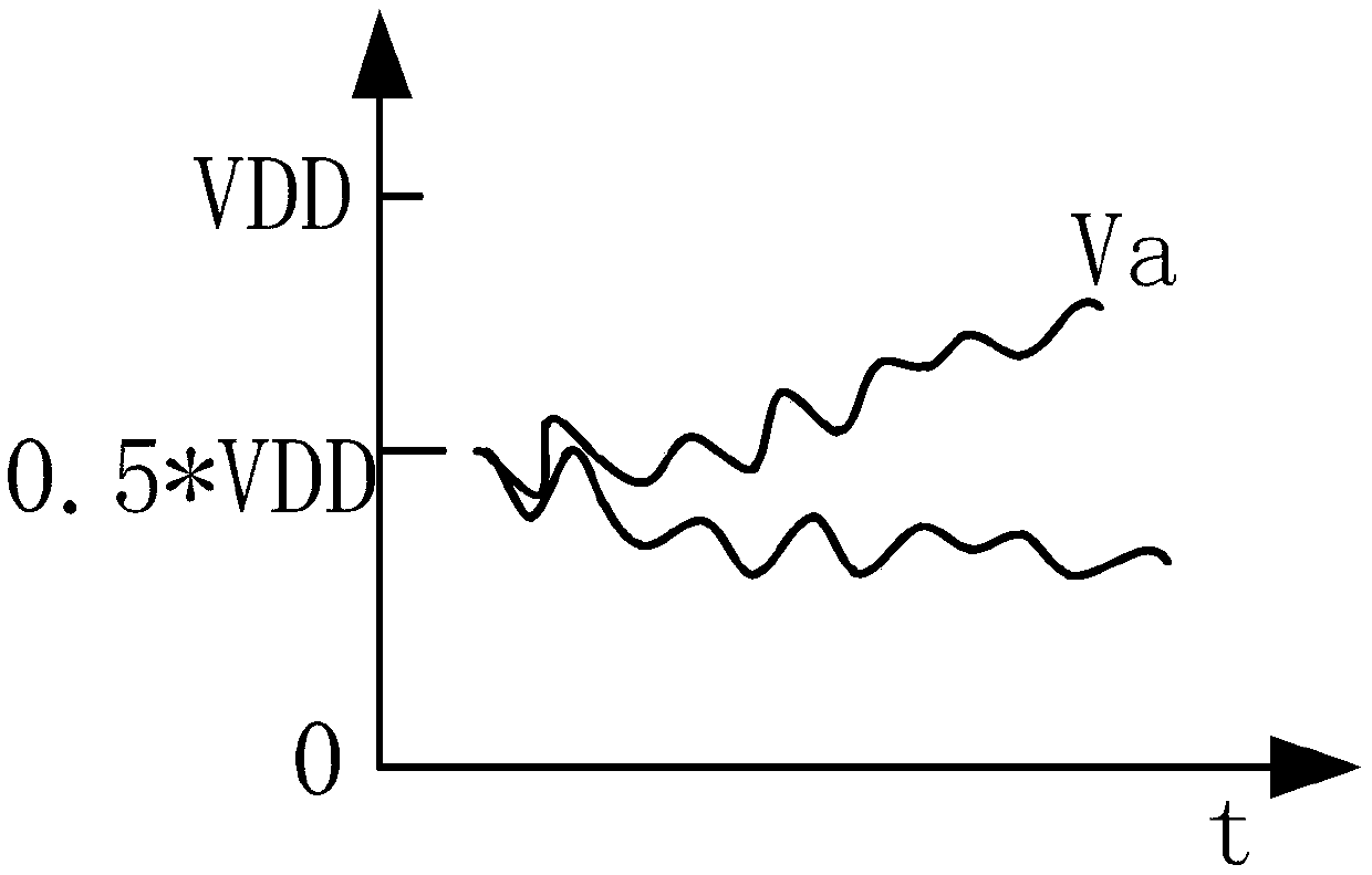
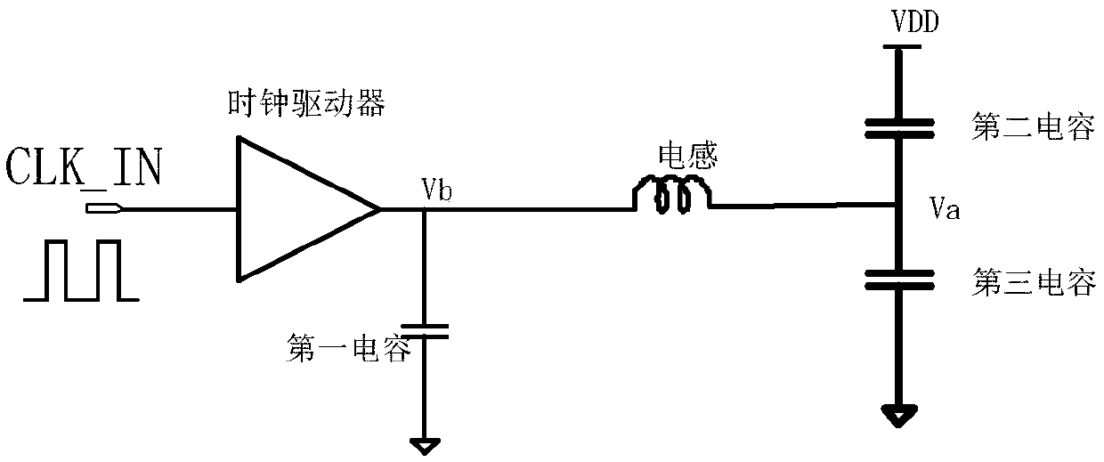
[0062] Such as Figure 5 As shown, the duty ratio adjustment device disclosed in Embodiment 1 includes a voltage detection circuit, an adjustment judgment circuit and a duty ratio correction circuit, wherein one end of the voltage detection circuit is connected to the first intermediate node Va, and the other end is connected to the adjustment The judgment circuit is used to detect the voltage value of the node Va, and output the detected voltage value to the adjustment judgment circuit. Theoretically, the voltage value of node Va should be half of the power supply voltage, that is, VDD / 2, but as introduced in the background technology, as Figure 4 As shown, since the node Va has different parasitic capacitance and resistance to the power supply voltage and the ground, the voltage value of the node Va will not be VDD / 2. If the supply voltage value is 1V, the theoretical node Va’s voltage value is 0.5V, and the actual node Va’s voltage value is 0.52V, which is higher than the...

Embodiment 2

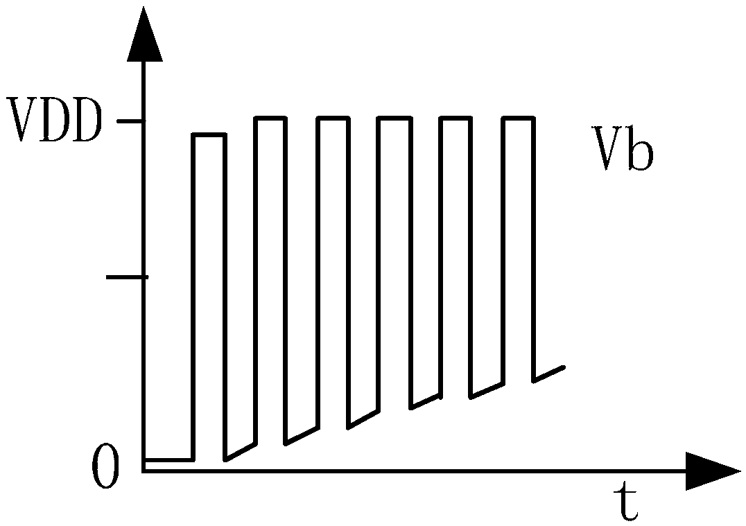
[0067] Such as Figure 6 As shown, the duty ratio adjustment device disclosed in Embodiment 2 includes a duty ratio detection circuit, an adjustment judgment circuit and a duty ratio correction circuit, wherein one end of the duty ratio detection circuit is connected to the above-mentioned second intermediate node Vb, The other end is connected with an adjustment judgment circuit for detecting the duty ratio of the clock signal at the node Vb, and outputting the detected duty ratio to the adjustment judgment circuit. Theoretically, the duty cycle of the clock signal at node Vb should be 1 / 2, but as introduced in the background technology, as Figure 4 As shown, due to the parasitic capacitance and resistance of the node Vb, the unequal driving capability of the clock driver and other factors, the duty cycle of the clock signal at the node Vb will be deviated. If the duty ratio of the clock signal at the actual node Vb is 0.6, ie higher than the theoretical duty ratio, the dut...

Embodiment 3

[0070] Such as Figure 7 As shown, the duty cycle adjustment device disclosed in Embodiment 3 includes a voltage detection circuit, a duty cycle detection circuit, an adjustment judgment circuit, and a duty cycle correction circuit, wherein one end of the voltage detection circuit is connected to the above-mentioned first intermediate node Va, the other end is connected to the adjustment judgment circuit, which is used to detect the voltage value of node Va, and output the detected voltage value to the adjustment judgment circuit; one end of the duty ratio detection circuit is connected to the above-mentioned second intermediate node Vb, and the other end is connected to the adjustment judgment circuit The circuit is used for detecting the duty ratio of the clock signal at the node Vb, and outputting the detected duty ratio to the adjustment judgment circuit. The principle and structure of the voltage detection circuit and the duty ratio detection circuit here are the same as ...


PUM


Abstract

The invention discloses a duty ratio adjusting device and method of a resonance system. The device comprises a resonance system and a duty ratio adjusting device connected with the resonance system, the resonance system comprises a clock driver, a first capacitor connected with the clock driver and an inductor connected with the first capacitor, and the other end of the inductor is connected withan intermediate point of a decoupling capacitor to form a first intermediate node; the duty ratio adjusting device is used for detecting the duty ratio of the clock signal output by the clock driver and / or detecting the voltage value of the first intermediate node, and adjusting the duty ratio of the clock signal input to the clock driver according to the duty ratio output by the clock driver and / or the voltage value of the first intermediate node. The circuit is simple in structure, can precisely adjust the duty ratio of a resonance system, and guarantees the integrity of a clock signal waveform to the maximum degree.

Description

technical field [0001] The invention relates to a duty ratio detection and adjustment technology, in particular to a duty ratio adjustment device and method for a resonant system. Background technique [0002] With the development of integrated circuit technology, the scale of the chip is getting bigger and bigger, and the clock mesh is getting bigger and bigger, which will bring problems of power consumption and clock skew. The LC resonant clock generates and distributes clock signals through the LC resonant circuit, which can better solve the problem of large-scale integrated circuit chips (such as processors, GPU (Graphics Processing Unit, graphics processor), FPGA (Field-Programmable Gate Array, field programmable Gate array), TPU (Tensorprocessing unit, tensor processor)) power consumption, clock skew and jitter problems. Wherein, the resonant frequency of the LC resonant clock f=1 / (2*π*sqrt(LC)). Among them, C is the equivalent parasitic capacitance of the clock grid...

Claims


Application Information

Patent Timeline
Patent Type & Authority Applications(China)
IPC IPC(8): H03K3/017
CPCH03K3/017
Inventor 李宗铭赵增华
Owner 苏州芯算力智能科技有限公司
Why Eureka
Try Eureka