A self-sufficient power supply circuit for flyback power converter

A technology of self-sufficient power supply and flyback power supply, which is applied in emergency protection circuit devices, conversion of AC power input to DC power output, electrical components, etc., and can solve problems such as burning control chips, large voltage ripples, and large bus voltage ripples , to achieve the effect of easy layout and wiring, increasing reliability and improving reliability

Active Publication Date: 2020-04-10
BEIJING RES INST OF PRECISE MECHATRONICS CONTROLS +1
View PDF2 Cites 0 Cited by
  • Summary
  • Abstract
  • Description
  • Claims
  • Application Information

AI Technical Summary

Problems solved by technology

These two methods are to obtain the power supply voltage required by the control chip after the bus voltage is divided. The problem is that because the bus voltage is affected by the grid voltage, the voltage ripple is relatively large, and the resistance is divided. Directly connecting to the power supply terminal of the control chip will cause the power supply voltage to be unstable, and the hiccup effect will easily occur. In addition, when the power converter has an abnormal short circuit, since the power supply voltage of the control chip is taken from the bus voltage, the control chip cannot start at this time. To the protective effect, it may even burn the control chip, which greatly reduces the reliability of the power converter
[0003] The power supply voltage of the flyback power converter control chip can be provided by the bus voltage power supply module. After the chip works normally, the auxiliary winding of the transformer can provide a stable chip power supply voltage, that is, the bus voltage power supply module and the auxiliary winding power supply module simultaneously provide Chip power supply, the disadvantage of this is that the bus voltage ripple is large and the auxiliary winding of the transformer has interference, which is not conducive to the stability of the chip power supply voltage

Method used


Image

  • A self-sufficient power supply circuit for flyback power converter

Examples


Embodiment Construction

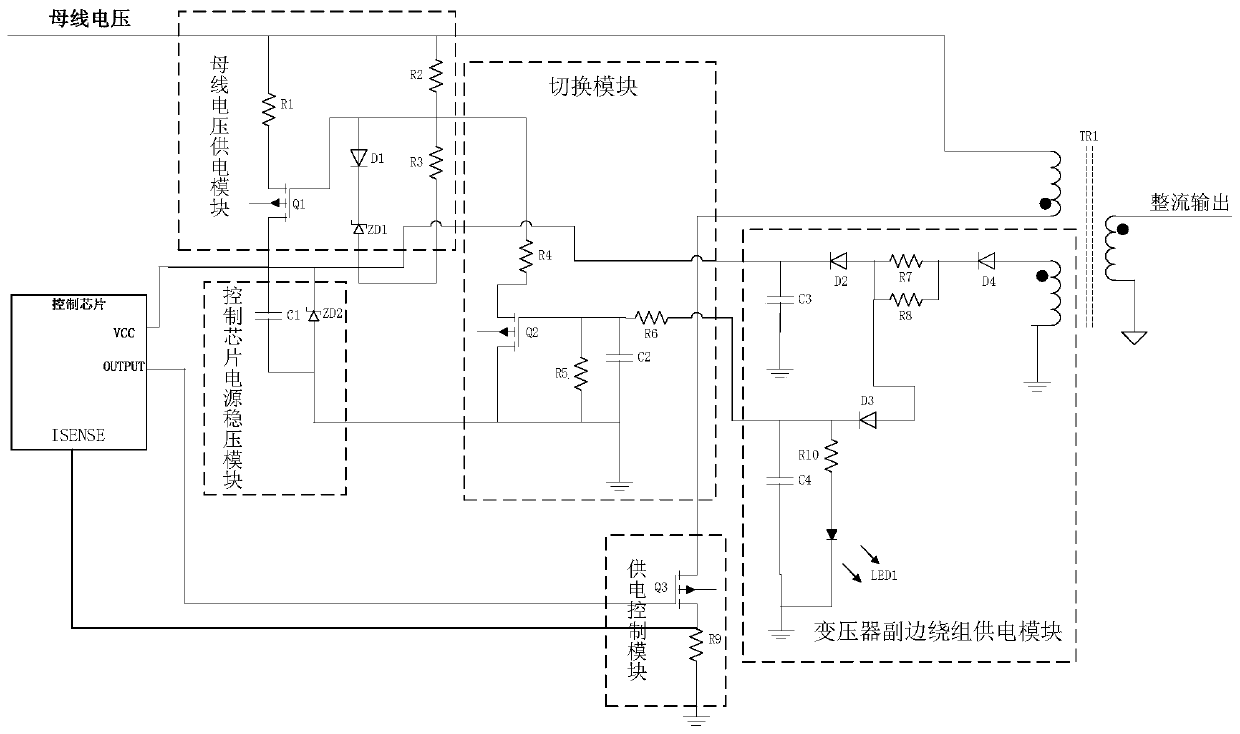
[0024] The self-sufficient power supply circuit is composed of a bus voltage power supply module, a secondary winding power supply module of a transformer, a voltage stabilizing module controlling a chip power supply, a transformer, a power supply control module and a switching module. The bus voltage power supply module supplies power to the control chip after the bus is powered on; after the control chip is powered on, it controls the operation of the primary winding of the transformer through the power supply control module, and rectifies and outputs electric energy through the secondary output winding; the secondary auxiliary winding of the transformer is coupled from the primary winding The voltage is obtained to supply power to the power supply module of the secondary winding of the transformer; the power supply module of the secondary winding of the transformer includes a first charging unit, a second charging unit and a switch unit, and the power supply module of the sec...


PUM


Abstract

The invention relates to a self-supply circuit for a flyback power converter. A bus voltage supply module supplies power to a control chip after the bus is powered on. After the control chip is powered on, the primary winding of the transformer is controlled to work by the power supply control module, and the secondary auxiliary winding of the transformer obtains voltage from the coupling of the primary winding to supply power to the secondary winding of the transformer. The power supply module of the secondary winding of the transformer is charged to supply power to the control chip. The switching module turns off the power supply output of the bus voltage supply module to the control chip after the secondary winding power supply module of the transformer is fully charged. After the powersupply module of the secondary winding of the transform is charged, The bus voltage is cut off, and the auxiliary winding supplies power to the control chip alone. If the power supply module of the secondary winding of the transformer fails or the PWM driving output duty ratio of the control chip is small, and the power supply control module is abnormal, etc., the fault recovery can be carried out, and the control chip can not be powered down.

Description

technical field [0001] The invention relates to a self-supporting power supply circuit for a flyback power converter, belonging to the technical field of power supply and distribution. Background technique [0002] The self-sufficient power supply circuit provides the power supply voltage required by the control chip without the need for external auxiliary power supply. Under normal circumstances, there are two ways to take power for a self-sufficient power supply circuit. One way is to get it through the voltage dividing resistor on the bus voltage, and the other way is to use the voltage converted from the bus voltage and the auxiliary winding of the transformer to the capacitor. Get charged. These two methods are to obtain the power supply voltage required by the control chip after the bus voltage is divided. The problem is that because the bus voltage is affected by the grid voltage, the voltage ripple is relatively large, and the resistance is divided. Directly connec...

Claims


Application Information

Patent Timeline
Patent Type & Authority Patents(China)
IPC IPC(8): H02M7/217H02H7/04
CPCH02H7/04H02M7/217
Inventor 岳长路王移川
Owner BEIJING RES INST OF PRECISE MECHATRONICS CONTROLS
Why Eureka
Try Eureka