Display device and backlight module thereof

A display device and backlight module technology, which is applied in lighting devices, fixed lighting devices, lighting auxiliary devices, etc., can solve the problems that the light beam cannot be used, it is difficult to meet the requirements of narrow borders, and it cannot be used as a display, etc., to achieve the reduction of non-display area effect

Active Publication Date: 2015-09-30
CORETRONIC DISPLAY SUZHOU CO LTD
View PDF12 Cites 0 Cited by
  • Summary
  • Abstract
  • Description
  • Claims
  • Application Information

AI Technical Summary

Problems solved by technology

[0004] In the above-mentioned liquid crystal display device 100, the support frame 127 used to support the liquid crystal display panel 110 is made of a light-shielding material, so the entire support portion 128 cannot transmit light, resulting in that the light beam emitted from the edge of the optical film 123 cannot be used, so The part of the liquid crystal display panel 110 relative to the supporting part 128 cannot be used as a display area
[0005] Since the top 132 of the front frame 130 will cover the non-display area of ​​the liquid crystal display panel 110, the top 132 needs to cover the entire support portion 128, resulting in the width D1 of the top 132 of the front frame 130 being too large (i.e., the frame is too wide), and it is difficult to fit a narrow frame. border needs

Method used


Image

  • Display device and backlight module thereof
  • Display device and backlight module thereof
  • Display device and backlight module thereof

Examples


Embodiment Construction

[0059] The aforementioned and other technical contents, features and effects of the present invention will be clearly presented in the following detailed description of a preferred embodiment with reference to the drawings. The directional terms mentioned in the following embodiments, such as: up, down, left, right, front or back, etc., are only directions referring to the attached drawings. Accordingly, the directional terms are used to illustrate and not to limit the invention.

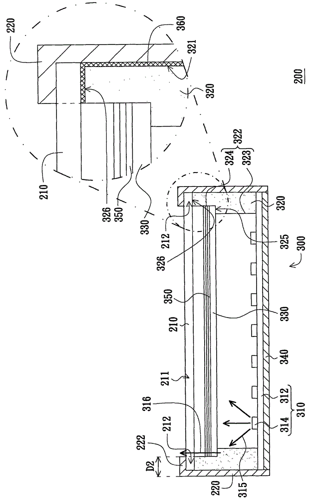
[0060] figure 2 It is a schematic diagram of a display device according to an embodiment of the present invention. Please refer to figure 2 , the display device 200 of this embodiment includes a display panel 210 and a backlight module 300 . The backlight module 300 includes a light source unit 310 , a supporting frame 320 and a diffusion plate 330 . The supporting frame 320 is made of transparent material and surrounds the light source unit 310 . An inner wall 322 of the supporting frame 320...


PUM


Abstract

Disclosed are a display device and a backlight module thereof. The backlight module comprises a light source unit, a supporting frame and an expansion board, wherein the supporting frame is made of a light-transmitting material and surrounds the light source unit, the inner wall of the supporting frame is in a stair-shaped structure, the stair-shaped structure comprises a first stair part and a second stair part which is located on the outside of the first stair part, the top face of the first stair part is a first bearing face, the top face of the second stair part is a second bearing face, and the second bearing face is higher than the first bearing face. The expansion board is assembled on the first bearing face and is located on the upper portion of the light source unit. Besides, the invention also discloses a display device using the backlight module. A display panel is assembled on the second bearing face. By the aid of the backlight module, the display device can meet the requirement of the narrow frame.

Description

【Technical field】 [0001] The present invention relates to a display device, and in particular to a display device using a non-self-luminous display panel and a backlight module thereof. 【Background technique】 [0002] The backlight module is used in conjunction with a non-self-illuminating display panel (such as a liquid crystal display panel) to provide the display light source required by the non-self-illuminating display panel. The technology related to the backlight module has been disclosed in many patent documents, such as China Taiwan Patent Publication No. 201003216 and No. 201009451 and US Patent Publication No. 20080291356 and other patent documents. [0003] figure 1 It is a schematic diagram of an existing liquid crystal display device using a direct-lit backlight module. Please refer to figure 1 , the conventional liquid crystal display device 100 includes a liquid crystal display panel 110 and a backlight module 120 disposed under the liquid crystal display ...

Claims


Application Information

Patent Timeline
Patent Type & Authority Patents(China)
IPC IPC(8): G02F1/13357F21S8/00F21V21/00
Inventor 刘绍鳯
Owner CORETRONIC DISPLAY SUZHOU CO LTD
Why Eureka
Try Eureka