
Electronic device

An electronic device and electrical connection technology, applied in the direction of electrical digital data processing, instruments, digital data processing components, etc., can solve the problems of increasing users, destroying the appearance of electronic devices, and losing color of electronic devices

Inactive Publication Date: 2013-05-08
INVENTEC CORP
View PDF0 Cites 2 Cited by
  • Summary
  • Abstract
  • Description
  • Claims
  • Application Information

AI Technical Summary

Problems solved by technology

However, this method has many disadvantages. In addition to requiring manual methods to increase the user's troubles, the use of additional covers will also damage the overall appearance of the electronic

Method used


Image

  • Electronic device
  • Electronic device
  • Electronic device

Examples


Embodiment Construction

[0031] Below in conjunction with accompanying drawing, structural principle and working principle of the present invention are specifically described:

[0032] The electronic device proposed in the embodiment achieves the effect of automatically covering or exposing the input / output port (I / O Port) mainly through the rotation of the rotating shaft mechanism. An embodiment is proposed below for detailed description, but it is only used for illustration and does not limit the protection scope of the present invention. Furthermore, in order to facilitate description and display of the technical features of the embodiments, the diagrams of the embodiments only show relevant components during implementation.

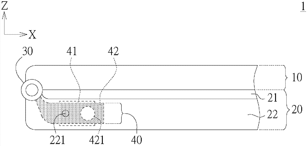
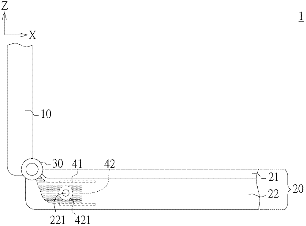
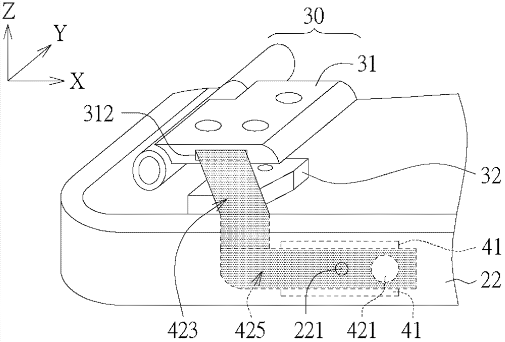
[0033] Please refer to Figure 1A , Figure 1B , which respectively illustrate the schematic diagrams of closing and opening of the electronic device according to an embodiment of the present invention. The electronic device 1, such as a notebook computer, includes a displa...


PUM


Abstract

An electronic device comprises a display module, a system module, a hinge group and a dustproof assembly. The system module is electrically connected with the display module, the system module is provided with a sliding groove and at least one input/output port, the hinge group is rotatably hinged with the display module and the system module to enable the display module to open and close relative to the system module, the dustproof assembly comprises a sliding groove and a covering piece, the sliding groove is located in the system module, one end of the covering piece is connected with the hinge group, and the other end of the covering piece is movably located at the position of the sliding groove. When the display module closes or opens relative to the system module, the hinge group drives the covering piece to enable the covering piece to relatively move in the sliding groove to respectively cover or expose the input/output port.

Description

technical field [0001] The present invention relates to an electronic device, and in particular to an electronic device with an automatic input / output port (I / O Port) dustproof mechanism. Background technique [0002] Current electronic devices such as notebook computers and other 3C devices, in order to be beautiful, dust-proof or prevent small insects from entering the I / O port, in the existing design, an additional cover such as a plastic partition is used. Board, or rubber sleeve (rubber) or empty cover (I / O dummy), etc. are fixed on the I / O port. When the I / O Port is not used, it is blocked. When the I / O Port needs to be used Then remove the cover to expose the I / O Port. However, there are many shortcomings in such an approach. In addition to requiring a manual method to increase the user's troubles, the use of an additional cover will also damage the overall appearance of the electronic device, making these shiny electronic devices lose their color a lot. Furthermore...

Claims


Application Information

Patent Timeline
IPC IPC(8): G06F1/16
Inventor 张信忠沈宜威
Owner INVENTEC CORP
Learn More