Low-heat coupling and non electromagnetic coupling dual-redundancy permanent-magnet synchronous motor between phase windings

An electromagnetic coupling and permanent magnet synchronization technology, which is applied to synchronous motors with stationary armatures and rotating magnets, magnetic circuit rotating parts, magnetic circuit stationary parts, etc., can solve the problem of large volume and weight and increase system parameters Changes and other issues, to achieve the effects of low thermal influence, improved reliability, and low thermal coupling

Active Publication Date: 2013-05-08
江苏盐新汽车产业投资发展有限公司
View PDF1 Cites 27 Cited by
  • Summary
  • Abstract
  • Description
  • Claims
  • Application Information

AI Technical Summary

Benefits of technology

This patented technology improves upon existing motors that have multiple layers of conducting materials due to its ability to reduce thermal interference without affecting their performance or causing damage during operation. By focusing on specific parts of the device called the rotating part (the inner ring) rather than just around them, this design reduces any unwanted interactions like eddy currents caused by rotation. Additionally, the use of an insulating material helps prevent leaks while still allowing for effective cooling. Overall, these technical improvements improve the efficiency and durability of electric machines used in power systems.

Problems solved by technology

This patented technical solution described for improving the reliabilty of magnetically driven devices involves incorporating multiple separate components into each component's space or reducing its size while still maintaining their functionality. These solutions aimed at increasing efficiency without adding too much mass or complexity.

Method used


Image

  • Low-heat coupling and non electromagnetic coupling dual-redundancy permanent-magnet synchronous motor between phase windings
  • Low-heat coupling and non electromagnetic coupling dual-redundancy permanent-magnet synchronous motor between phase windings
  • Low-heat coupling and non electromagnetic coupling dual-redundancy permanent-magnet synchronous motor between phase windings

Examples


Embodiment Construction

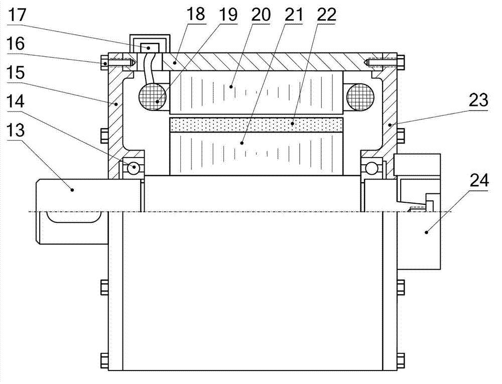
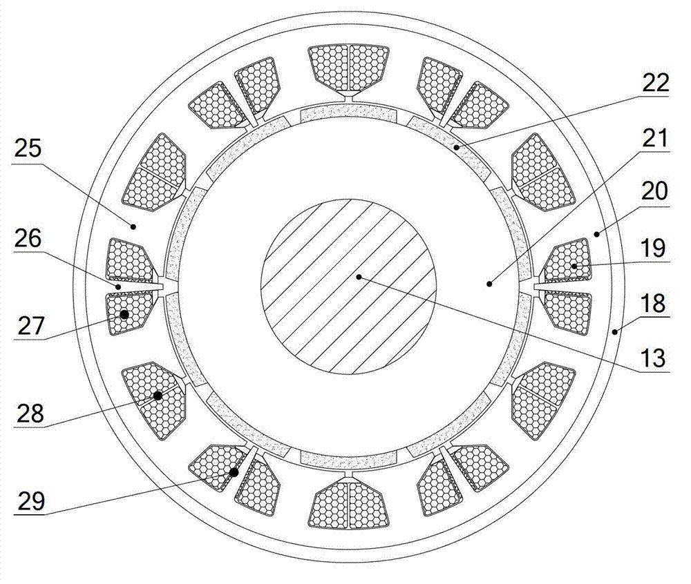
[0025] The double redundancy permanent magnet synchronous motor with low thermal coupling and no electromagnetic coupling among the windings of each phase of the present invention will be described in detail below in combination with the embodiments and the accompanying drawings.

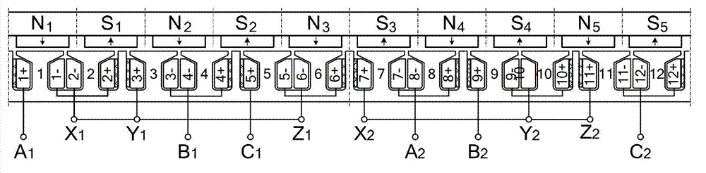
[0026] The double-redundant permanent magnet synchronous motor with low thermal coupling and no electromagnetic coupling between the windings of each phase of the present invention is mainly achieved by selecting the number Z of large teeth on the stator of the three-phase permanent magnet synchronous motor. 0 (Multi-turn coils are wound on each large tooth) and the number of pole pairs of the permanent magnet rotor p 0 Coordination between, the number of motor phases is 3, Z 0 is an even number, p 0 is an odd number, Z 0 with p 0 There is no common divisor between them, and there exists Z 0 =2p 0 The relationship of ±2; and there are 6 small teeth arranged on the stator core, and there are 12 ...


PUM


Abstract

The invention discloses a low-heat coupling and non electromagnetic coupling dual-redundancy permanent-magnet synchronous motor between phase windings. Two sets of mutually independent three-phase symmetrical windings are placed on a stator core. Two controllers independently supply power for the two sets of windings. The two sets of windings can work together or work respectively and independently. Each coil of each phase winding is a concentrated winding, and the end portions of the windings are not overlapped. Due to the fact that small teeth are arranged and heat resistant thermal insulation materials are placed on two sides of the small teeth, the phase winding is separated from an electric angle, therefore leakage mutual inductance which corresponds to leakage magnetic fields which are arranged between the phase windings and on end portions is small, and no inter-groove leakage inductance appears. Meanwhile, thermal coupling between the phase windings is low. An even number of coils of an even number are continuously winded and connected in series on the periphery of a stator according to a rule of repeated winding and rewinding. Mutual inductance between the phase windings which correspond to armature reaction magnetic fields is small, approximately no electromagnetic coupling exists between the phase windings, and reliability is improved.

Description


Claims


Application Information

Patent Timeline
Owner 江苏盐新汽车产业投资发展有限公司
Why Eureka
Try Eureka