Double y-phase shift 30° without electromagnetic coupling between windings of each phase Double redundant permanent magnet synchronous motor

A permanent magnet synchronous motor, electromagnetic coupling technology, applied in the shape/style/structure of winding conductors, electromechanical devices, electrical components, etc., can solve the problems of large volume and weight, high harmonic components of armature reaction magnetomotive force, etc. , to achieve the effect of low thermal coupling, no slot mutual leakage inductance, and small leakage mutual inductance

Active Publication Date: 2019-11-05
TIANJIN UNIV
View PDF4 Cites 0 Cited by
  • Summary
  • Abstract
  • Description
  • Claims
  • Application Information

AI Technical Summary

Problems solved by technology

Although the parallel structure double redundancy permanent magnet synchronous motor solves the problem of large volume and weight, some parallel structure double redundancy permanent magnet synchronous motors still have electromagnetic coupling between the two sets of windings; some parallel structure double redundancy permanent magnet Although the electromagnetic coupling is eliminated between the two sets of windings of the synchronous motor, the double-redundancy permanent magnet synchronous motor with double-redundancy permanent magnet synchronous motor has low thermal coupling and no electromagnetic coupling between the phase windings of the double Y phase shift. Harmony of the armature reaction magnetomotive force The wave component is high, and its performance needs to be further improved

Method used


Image

  • Double y-phase shift 30° without electromagnetic coupling between windings of each phase Double redundant permanent magnet synchronous motor
  • Double y-phase shift 30° without electromagnetic coupling between windings of each phase Double redundant permanent magnet synchronous motor
  • Double y-phase shift 30° without electromagnetic coupling between windings of each phase Double redundant permanent magnet synchronous motor

Examples


Embodiment Construction

[0030] The following is a detailed description of the double redundant permanent magnet synchronous motor with double Y phase shift of 30° and no electromagnetic coupling between the windings of each phase of the present invention in combination with the embodiments and accompanying drawings.

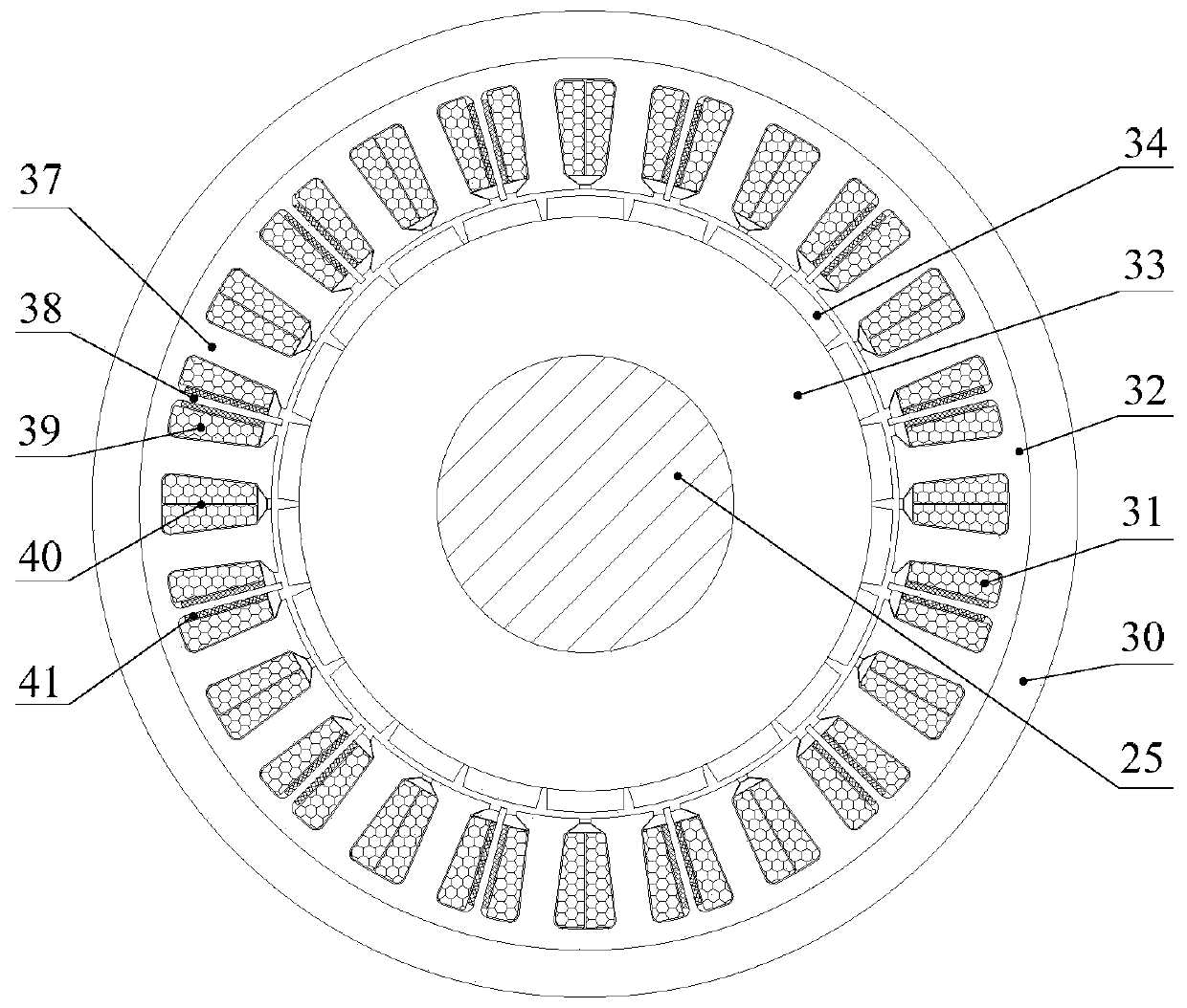
[0031] In the present invention, there is no electromagnetic coupling between the phase windings of the double Y phase shift of 30°, and the double redundant permanent magnet synchronous motor is mainly through the selection of the number Z of large teeth on the stator of the six-phase permanent magnet synchronous motor. 0 (Multi-turn coils are wound on each large tooth) and the number of pole pairs of the permanent magnet rotor p 0 Coordination between, the number of motor phases is 6, Z 0 is an even number, p 0 is an odd number, Z 0 with p 0 There is no common divisor between them, and there exists Z 0 = 2p 0 The relationship of ±2; and there are 12 small teeth arranged on the st...


PUM


Abstract

The invention discloses a double-Y 30 DEG phase shift dual-redundancy permanent magnet synchronous motor without electromagnetic coupling between two phases of windings. Two sets of independent three-phase symmetrical windings are placed on a stator core, the phase difference of the electromotive force between the corresponding phases of each three-phase symmetrical winding is 30 DEG electrical angle, the two sets of windings are powered by two controllers independently, and the two sets of windings can work simultaneously or separately. The coils of each phase of winding are concentrated windings, and the winding ends do not overlap. Moreover, by placing small teeth and placing high-temperature-resistant insulation materials on both sides of the small teeth, the two phases of windings areelectrically isolated from each other, the leakage mutual inductance between the two phases of windings corresponding to an end leakage magnetic field is extremely small, and there is no groove mutual leakage inductance, and at the same time, the thermal coupling between the two phases of windings is low. The mutual inductance between the two phases of windings corresponding to an armature reaction magnetic field is extremely small, and it can be assumed that there is no electromagnetic coupling between the two phases. During double redundancy operation, the armature reaction in the motor hasa low magnetomotive force harmonic component.

Description

technical field [0001] The invention relates to a double redundancy permanent magnet synchronous motor. In particular, it relates to a double-redundancy permanent magnet synchronous motor with low thermal coupling and no electromagnetic coupling between windings of each phase with 2Y phase shift of 30°. Background technique [0002] The permanent magnet synchronous motor has many advantages. In the electric drive system that does not allow downtime operation, the use of double redundancy permanent magnet synchronous motor can improve the reliability of the system. At present, double redundancy permanent magnet synchronous motors generally adopt two structural forms including parallel connection and series connection. Among them, the double-redundancy permanent magnet synchronous motor with series structure is to install two sets of independent stators and rotors coaxially. Its volume and weight are relatively large, and it is difficult to coordinate and control the redundan...

Claims


Application Information

Patent Timeline
Patent Type & Authority Patents(China)
IPC IPC(8): H02K3/28
CPCH02K3/28H02K2213/03
Inventor 陈益广杨玉凯沈勇环
Owner TIANJIN UNIV
Why Eureka
Try Eureka