
Roof structure with airflow channel

A roof structure and airflow channel technology, which is applied to building roofs, roof ventilation, ventilation systems, etc., can solve the problems of large-area bulging, cracking and rain leakage on the roof, achieve good rain leakage prevention effect, promote internal and external exchange, prevent The effect of gas expansion

Active Publication Date: 2013-05-15
STATE GRID HEBEI ELECTRIC POWER CO LTD +1
View PDF6 Cites 1 Cited by
  • Summary
  • Abstract
  • Description
  • Claims
  • Application Information

AI Technical Summary

Problems solved by technology

[0004] The purpose of the present invention is to provide a roof structure with airflow channels to solve the

Method used


Image

  • Roof structure with airflow channel

Examples


Example Embodiment

[0012] The present invention will be further described in detail below with reference to the accompanying drawings and specific embodiments.

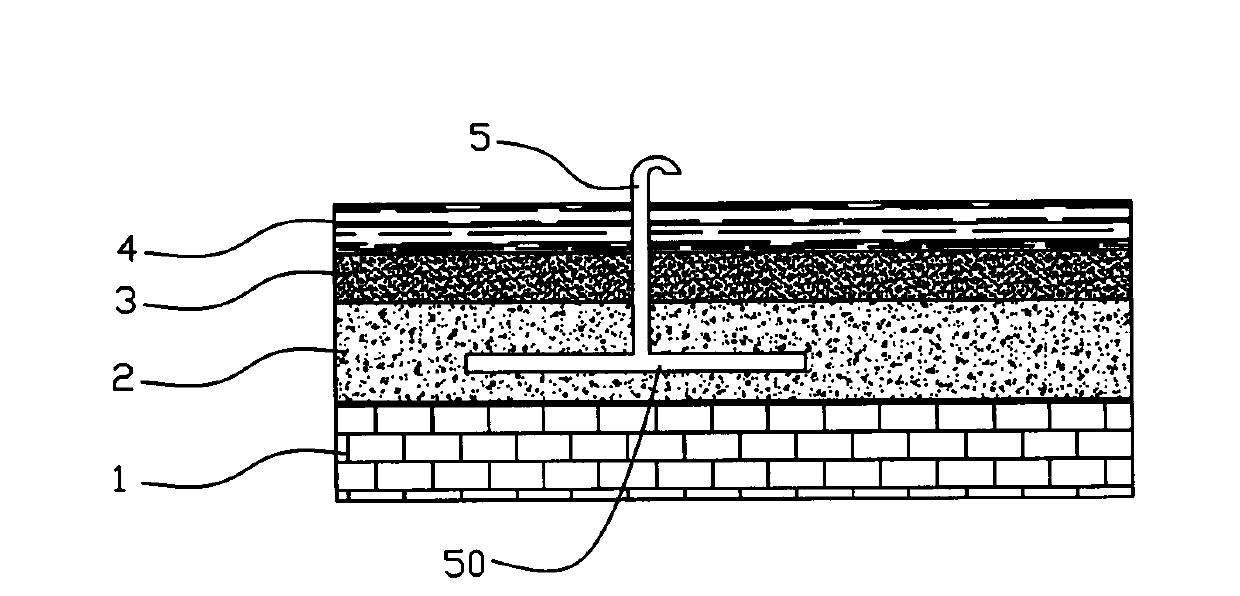
[0013] figure 1 The cross-sectional structure of the preferred embodiment of the present invention is schematically shown. As shown in the figure, the preferred embodiment includes a prefabricated board layer 1, a carbon slag layer 2, a cement layer 3 and an asphalt felt layer 4 sequentially arranged from bottom to top. In order to make the gas in the carbon slag layer 2 communicate with the outside, the preferred embodiment further includes a vertically arranged air duct 5, the lower end of the air duct 5 extends through the cement layer 3 and the asphalt felt layer 4 to the carbon slag layer 2, the upper end of the air duct 5 is bent downward to prevent rainwater from entering the carbon residue layer 2.

[0014] If the air duct 4 is not provided, for the roof without the asphalt linoleum layer 4, the prefabricated board layer 1 unde...


PUM


Abstract

The invention provides a roof structure with an airflow channel. The roof structure with the airflow channel comprises a pre-arranged plate layer, a carbon residue layer and a cement layer, wherein the pre-arranged plate layer, the carbon residue layer and the cement layer are sequentially placed from the bottom up. The roof structure with the airflow channel further comprises an air-guide pipe vertically arranged, wherein the lower end of the air-guide pipe penetrates through the cement layer and extends into the carbon residue layer, and the upper end of the air-guide pipe bends downwards. The air-guide pipe can facilitate inside-outside air exchange inside the carbon residue layer and prevent air gas expansion, and therefore a bloating phenomenon of the cement layer is avoided, and correspondingly, the cracking phenomenon caused by the bloating does not exist any more, and accordingly, good rain-leakage-proof effects can be well achieved.

Description

technical field [0001] The invention relates to a layered roof structure, in particular to a layered roof structure with airflow channels. Background technique [0002] At present, many roofs are composed of three layers of prefabricated slab layer, carbon residue layer and cement layer. During the roof construction, due to the large roof area, especially the roof with a large building volume, the construction of the entire roof cannot be completed in one go. After the construction is completed, although the exterior of the roof is finished flat and smooth, the central part may suffer from bulging, cracks, and rain leakage after a short period of time due to the lack of uniformity in the processing time and materials used. [0003] In order to solve the problem of roof leakage, most roofs may undergo expensive asphalt waterproofing projects, but after a short period of use, the cement layer and asphalt layer of the roof may bulge again in a large area, and some places even ...

Claims


Application Information

Patent Timeline
IPC IPC(8): E04D13/17E04D11/02
Inventor 张立志陈同兴王永生郭笑萌
Owner STATE GRID HEBEI ELECTRIC POWER CO LTD
Learn More