
Pixel circuit of active organic electroluminescent display and programming method of pixel circuit
A pixel circuit and luminescence technology, applied in static indicators, instruments, etc., can solve the problems of uneven brightness display of AMOLED, difficult to apply high display specifications and large information display occasions, etc., to achieve improved programming speed and high contrast Effect
- Summary
- Abstract
- Description
- Claims
- Application Information
AI Technical Summary
Problems solved by technology
Method used
Image

Examples
Embodiment 1
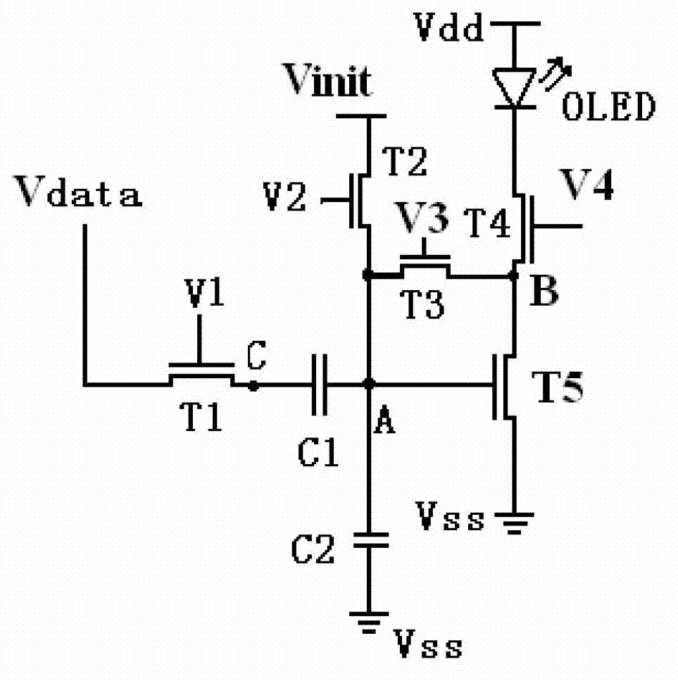
[0036] Such as figure 1 As shown, the pixel circuit of the active organic electroluminescent display in this embodiment includes a first transistor T1, a second transistor T2, a third transistor T3, a fourth transistor T4, a fifth transistor T5, an organic light emitting diode OLED, a A capacitor C1 and a second capacitor C2.
[0037] Each transistor includes a gate, drain and source.
[0038] The drain of the first transistor is connected to the data line, and the source of the first transistor is connected to the first plate of the first capacitor ( figure 1 Point C is a point between the source of the first transistor and the first plate of the first capacitor), and the gate of the first transistor is connected to the first scanning control line V1.
[0039] The drain of the second transistor is connected to the initial voltage line Vinit, the source of the second transistor is connected to the second plate of the first capacitor, and the gate of the second transistor is co...
Embodiment 2
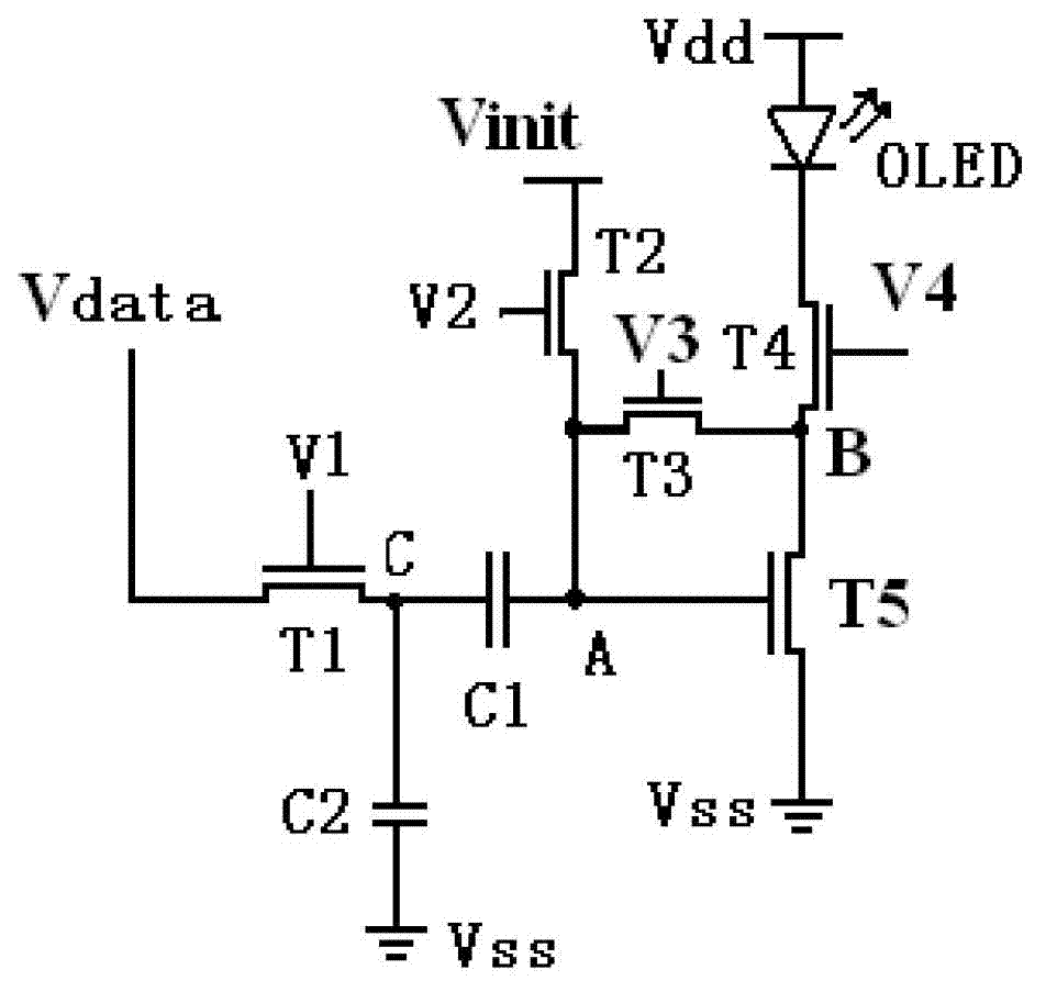
[0063] Such as image 3 As shown, the pixel circuit of the active organic electroluminescent display of this embodiment is the same as that of Embodiment 1 except for the following features:
[0064] In Embodiment 1, "the second plate of the first capacitor is grounded through the second capacitor" is replaced with "the first plate of the first capacitor is grounded through the second capacitor".
[0065] The programming method of the pixel circuit of the active organic electroluminescence display of the present embodiment:
[0066] For the first frame period, the programming steps are as follows:
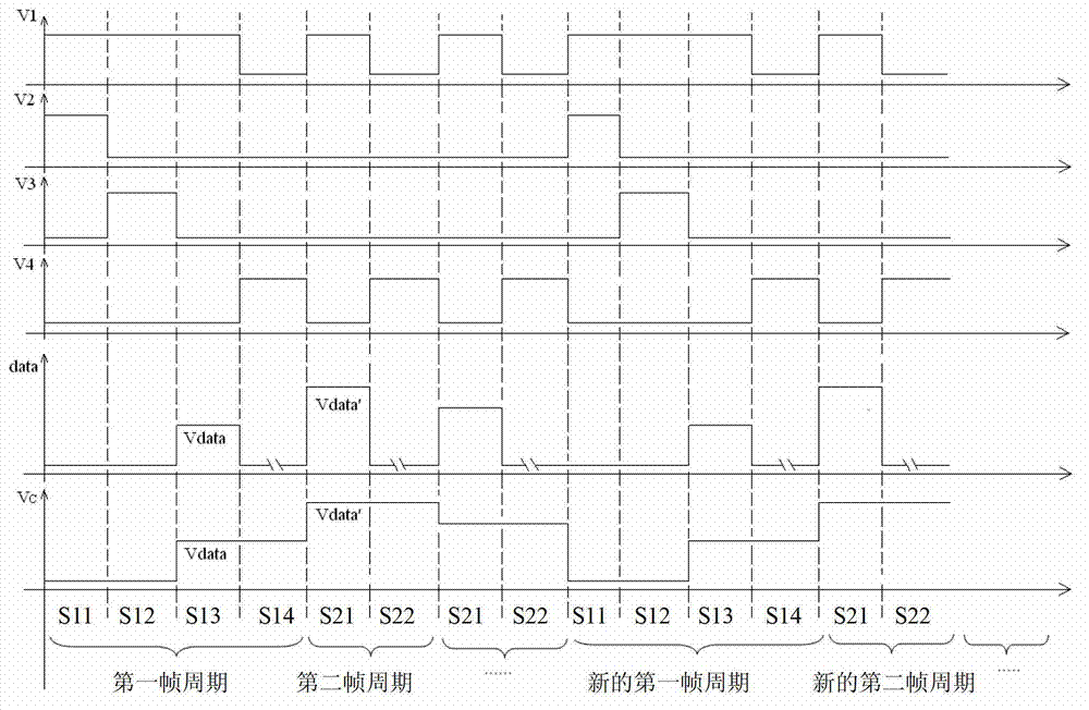
[0067] S11 initialization: control the gate voltage V1 of the first transistor, the gate voltage V2 of the second transistor to be high level, the gate voltage V3 of the third transistor, and the gate voltage V4 of the fourth transistor to be low level, and the data line Voltage V data is zero level, the value of the initial voltage Vinit is greater than the threshold voltage of...
PUM
 Abstract
Description
Claims
Application Information