Method for calculating combined stress of annular valve sheet of shock absorber

A technology of composite stress and calculation method, applied in the field of hydraulic shock absorbers, can solve the problems of inability to calculate the composite stress of valve plates, inability to provide accurate analytical calculation formulas and calculation methods, and inability to meet the requirements of shock absorbers.

Inactive Publication Date: 2013-06-12
SHANDONG UNIV OF TECH
View PDF1 Cites 8 Cited by
  • Summary
  • Abstract
  • Description
  • Claims
  • Application Information

AI Technical Summary

Problems solved by technology

[0002] For the calculation of the composite stress of the shock absorber annular valve plate, there were no accurate and reliable calculation methods at home and abroad. Most of them used finite element simulation software to numerically simulate the composite stress of the valve plate under a given pressure by establishing a solid model. Reliable numerical solutions can be obtained, but solid models need to be established and accurate analytical calculation formulas and calculation methods cannot be provided, so it cannot meet the requirements of the rapid development of the modern automobile industry and the modern CAD design of shock absorbers
Although the "Mechanical Design Manual" provides the maximum stress calculation formula, an approximate stress coefficient can only be obtained from the manual based on the ratio of the inner and outer radius of the valve plate, and the maximum stress of the valve plate can be approximated, but it cannot be used for any radius of the valve plate. Composite stresses at locations are calculated

Method used


Image

  • Method for calculating combined stress of annular valve sheet of shock absorber
  • Method for calculating combined stress of annular valve sheet of shock absorber
  • Method for calculating combined stress of annular valve sheet of shock absorber

Examples


Embodiment 1

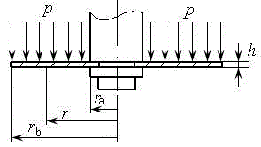
[0037] Embodiment one: The thickness of a shock absorber valve plate h =0.3mm, inner circle radius =5.0mm, outer circle radius =8.5mm, Poisson's ratio mu =0.3, the uniform pressure is p =1.0MPa, p =2.0MPa and p =3.0MPa.

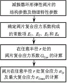
[0038] The calculation method of the composite stress of the shock absorber annular valve plate provided by the example of the present invention, the calculation process is as follows figure 1 As shown, the specific steps are as follows:

[0039] (1) Determine the constant terms of the composite stress coefficient of the valve plate E 1 , E 2 , E 3 with E 4

[0040] According to the radius of the inner circle of the damper valve plate =5.0mm, outer circle radius =8.5mm, elastic modulus E =2.0 and Poisson's ratio mu =0.3, to determine the various constants formed by the composite stress coefficient of the valve plate under uniform pressure E 1 , E 2 , E 3 with E 4 ,which is:

[0041] , ,

[0042] ,

[0043] = ; ...

Embodiment 2

[0062] Embodiment two: The thickness of a shock absorber annular valve plate h =0.3mm, inner circle radius =5.0mm, outer circle radius =8.75mm, Poisson's ratio mu =0.3, uniform pressure p =3.0MPa.

[0063] Using the calculation steps of Embodiment 1, according to the inner circle radius of the shock absorber annular valve plate =5.0mm, outer circle radius =8.75mm, Poisson's ratio mu =0.3, to determine the various constants formed by the composite stress coefficient of the annular valve plate E 1 , E 2 , E 3 and E 4 ,which is:

[0064] , ,

[0065] ,

[0066] = ;

[0067] In the formula, , , , , , , , ;

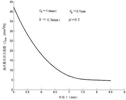
[0068] Composite stress coefficient of shock absorber annular valve plate calculated in this embodiment with radius r ( ) change curve, such as Figure 7 shown; when the pressure p =3.0MPa, the calculated composite stress of the shock absorber annular valve plate curves, such as Figure 8 Shown, inner circle radius ...

Embodiment 3

[0071] Embodiment three: The structural parameters and material performance parameters of a shock absorber annular valve plate are exactly the same as those in Example 2, only the applied uniform pressure p =4.0MPa is different from that of the examples.

[0072] Using the calculation steps of the second embodiment, the annular valve plate of the shock absorber in the third embodiment is under uniform pressure p =4.0MPa composite stress is calculated; since the structural parameters and material performance parameters of the annular valve plate of the shock absorber are exactly the same as those in Example 2, the various constants formed by the composite stress coefficient of the annular valve plate ( E 1 , E 2 , E 3 and E 4 ) and composite stress coefficient Exactly the same as that of embodiment two.

[0073] in uniform pressure p =4.0MPa, the calculated composite stress of the shock absorber annular valve plate curves, such as Figure 10 shown, using the inn...


PUM


Abstract

The invention relates to a method for calculating the combined stress of an annular valve sheet of a shock absorber, and belongs to the technical field of shock absorbers. Previously, no reliable method for calculating the combined stress of the annular valve sheet is provided all the time, mostly the numerical simulation operation is carried out by ANSYS, and the modern CAD (computer aided design) requirements of the shock absorber cannot be met. The method is characterized by comprising the following steps: 1) determining constant terms comprising combined stress coefficients; 2) calculating the combined stress coefficient at any radius r; and 3) calculating the combined stress of the valve sheet at any radius r. According to the method, the combined stress at any radius and the maximal combined stress at the radius of an inner circle can be calculated according to the structure and material property parameters and the stress of the annular valve sheet of the shock absorber; the ANSYS simulation result shows that the method for calculating the combined stress of the annular valve sheet of the shock absorber is accurate; and a reliable combined stress calculating method is provided for the split design and the stress intensity checking of the annular sandwich valve sheet of the shock absorber.

Description

technical field [0001] The invention relates to a hydraulic shock absorber, in particular to a calculation method for the composite stress of the annular valve plate of the shock absorber. Background technique [0002] For the calculation of the composite stress of the shock absorber annular valve plate, there is no accurate and reliable calculation method at home and abroad. Most of them use finite element simulation software to numerically simulate the composite stress of the valve plate under a given pressure by establishing a solid model. Reliable numerical solutions can be obtained, but solid models need to be established and accurate analytical calculation formulas and calculation methods cannot be provided, so it cannot meet the requirements of the rapid development of the modern automobile industry and the modern CAD design of shock absorbers. Although the "Mechanical Design Manual" provides the maximum stress calculation formula, an approximate stress coefficient c...

Claims


Application Information

Patent Timeline
Patent Type & Authority Applications(China)
IPC IPC(8): G06F17/50
Inventor 周长城刘小亭提艳
Owner SHANDONG UNIV OF TECH
Why Eureka
Try Eureka