Calculation Method of Composite Stress of Shock Absorber Valve Plate Under Arbitrary Axisymmetric Non-uniform Pressure

A technology of non-uniform pressure and compound stress, applied in the field of hydraulic shock absorbers, can solve the problem of failure to provide accurate and reliable, shock absorber valve plate breakage, and it is difficult to meet the precise design and strength calibration of shock absorbers and superimposed valve plates. nuclear and other issues

Inactive Publication Date: 2016-10-12
SHANDONG UNIV OF TECH
View PDF2 Cites 0 Cited by
  • Summary
  • Abstract
  • Description
  • Claims
  • Application Information

AI Technical Summary

Problems solved by technology

However, in order to realize the stress intensity calculation of the shock absorber valve plate under any axisymmetric non-uniform pressure, it is necessary to solve the calculation problem of the composite stress of the valve plate first, and the composite stress will cause the shock absorber valve plate to break at the radius of the inner circle
However, at present, there is no accurate and reliable calculation method for the calculation of the composite stress of the shock absorber valve plate under the axisymmetric non-uniform pressure at home and abroad, and most of them are based on the uniform pressure on the shock absorber valve plate Composite stress is calculated, because there is a certain difference between the calculated composite stress value of the valve plate and the actual value, therefore, it is difficult to meet the requirements of precise design and strength check of the shock absorber and superimposed valve plate

Method used


Image

  • Calculation Method of Composite Stress of Shock Absorber Valve Plate Under Arbitrary Axisymmetric Non-uniform Pressure
  • Calculation Method of Composite Stress of Shock Absorber Valve Plate Under Arbitrary Axisymmetric Non-uniform Pressure
  • Calculation Method of Composite Stress of Shock Absorber Valve Plate Under Arbitrary Axisymmetric Non-uniform Pressure

Examples


Embodiment 1

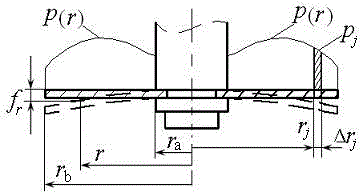
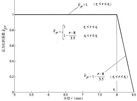
[0053] Example 1: The radius r of the inner circle of a ring valve plate of a shock absorber a =5.0mm, outer circle radius r b =8.5mm, elastic modulus E=2.0×10 11 Pa and Poisson's ratio μ=0.3, thickness h=0.3mm, valve port radius r o =8.0mm, apply uniform pressure p in the radius [5.0,8.0]mm section 0 =3.0MPa, apply linear non-uniform pressure on the [8.0,8.5]mm section Calculate the composite stress of the damper valve plate under this pressure.

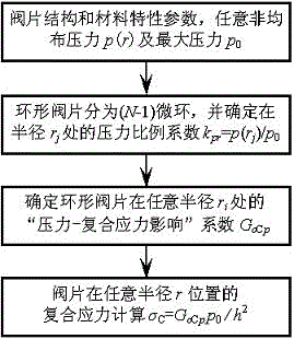
[0054] The calculation method of the composite stress of the damper valve plate under any axisymmetric non-uniform pressure provided by the example of the present invention, the calculation process is as follows figure 2 As shown, the specific steps are as follows:

[0055] (1) Determined at the radius r j The microannular pressure proportional coefficient k at prj :

[0056] According to non-uniform pressure and its maximum value is p 0 =3.0MPa, the radius r of the inner circle of the damper valve plate a =5.0mm, outer...

Embodiment 2

[0084] Embodiment 2: The thickness of a shock absorber valve plate is h=0.3mm, and the radius of the inner circle is r a =5.0mm, outer circle radius r b =8.5mm, elastic modulus E=2.0×10 11 Pa and Poisson's ratio μ = 0.3, in [r a ,r b ] within the range of the secondary non-uniform pressure Calculate the composite stress of the damper valve plate under this pressure.

[0085] The calculation steps of Embodiment 1 are adopted, namely:

[0086] (1) Determined at the radius r j The microannular pressure proportional coefficient k at prj :

[0087] According to non-uniform pressure and its maximum value is p 0 =3.0MPa, the radius r of the inner circle of the damper valve plate a =5.0mm, outer circle radius r b =8.5mm, the radius interval [r a ,r b ] are equally divided into 70 parts, i.e. 70 microrings, the number of radius N=71; the width Δr=0.05mm of each microring; j The inner radius r of the microring at kj = r j , outer circle radius r tj = r kj +Δr=r j+1 ...

Embodiment 3

[0106] Embodiment 3: The structural parameters and material characteristic parameters of a shock absorber valve plate are the same as those in Embodiment 1, that is, the thickness h=0.3mm, and the inner circle radius r a =5.0mm, outer circle radius r b =8.5mm, elastic modulus E=2.0×10 11 Pa and Poisson's ratio μ = 0.3, in [r a ,r b ] within the range of applied sinusoidal non-uniform pressure Calculate the composite stress of the damper valve plate under this pressure.

[0107] The calculation steps of Embodiment 1 are adopted, namely:

[0108] (1) Determined at the radius r j The microannular pressure proportional coefficient k at prj :

[0109] According to non-uniform pressure and its maximum value is p 0 =3.5MPa, the radius r of the inner circle of the damper valve plate a =5.0mm, outer circle radius r b =8.5mm, the radius interval [r a ,r b ] are evenly divided into 70 parts, that is, 70 microrings, the number of radiuses N=71, and the width of each microri...


PUM


Abstract

The invention relates to a calculation method for the composite stress of a shock absorber valve plate under arbitrary axisymmetric non-uniform pressure, and belongs to the technical field of shock absorbers. Previously, no reliable calculation method has been given for the composite stress of the shock absorber valve plate under any axisymmetric non-uniform pressure at home and abroad. The invention is characterized in that any axisymmetric non-uniform pressure is divided into multiple micro-ring pressures, and the proportional coefficient of each micro-ring pressure is determined; then, the product of the composite stress coefficient under the micro-ring pressure and the micro-ring pressure proportional coefficient After superposition, the "pressure-composite stress influence" coefficient of the valve plate at any radius is obtained, so as to realize the calculation of the composite stress of the shock absorber valve plate at any radial position under any axisymmetric non-uniform pressure. Through examples and ANSYS simulation verification, it can be seen that this calculation method is accurate, and it provides a reliable calculation of the composite stress of the shock absorber valve plate under any axisymmetric non-uniform pressure for the precise design and strength check of the shock absorber and the superimposed valve plate. Calculation method.

Description

technical field [0001] The invention relates to a hydraulic shock absorber, in particular to a method for calculating the composite stress of a shock absorber valve plate under any axisymmetric non-uniform pressure. Background technique [0002] Due to the influence of the normal through hole and the annular gap, the annular valve plate of the shock absorber is actually subjected to non-uniform pressure, and may even be irregularly distributed. However, in order to realize the stress intensity calculation of the shock absorber valve plate under any axisymmetric non-uniform pressure, it is necessary to solve the calculation problem of the composite stress of the valve plate first, and the composite stress will cause the shock absorber valve plate to break at the radius of the inner circle . However, at present, there is no accurate and reliable calculation method for the calculation of the composite stress of the shock absorber valve plate under the axisymmetric non-uniform ...

Claims


Application Information

Patent Timeline
Patent Type & Authority Patents(China)
IPC IPC(8): G06F17/50
Inventor 周长城赵雷雷宋群
Owner SHANDONG UNIV OF TECH
Why Eureka
Try Eureka