Method for forming thin-walled molded product

A thin-formed product and process technology, applied in the direction of flat products, household appliances, other household appliances, etc., can solve problems such as unavailability, deterioration of optical properties, increase in weight, etc., achieve smooth compression process, prevent residual residual stress, and alleviate Effects of deviations in pressure distribution

Active Publication Date: 2013-06-19
JAPAN STEEL WORKS LTD
View PDF5 Cites 7 Cited by
  • Summary
  • Abstract
  • Description
  • Claims
  • Application Information

AI Technical Summary

Problems solved by technology

In the case of a light guide plate, if the plate thickness is not uniform, the optical characteristics will deteriorate and cannot be used.
In order to avoid such a problem when molding a medium-sized or larger light guide plate, conventionally it was necessary to increase the plate thickness and increase the weight

Method used


Image

  • Method for forming thin-walled molded product
  • Method for forming thin-walled molded product
  • Method for forming thin-walled molded product

Examples


Embodiment Construction

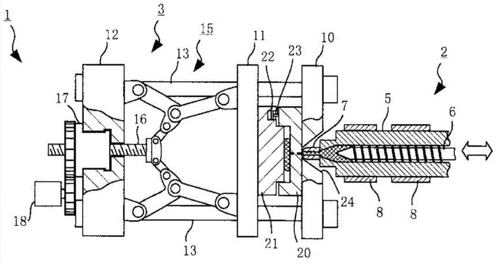
[0029] The molding method of the thin molded article of this embodiment can be performed by a conventionally known injection molding machine. In this embodiment, a method of molding a medium-sized or larger light guide plate for liquid crystal with the electric injection molding machine 1 will be described, but the electric injection molding machine 1 will be schematically described. Such as figure 1 As shown, the electric injection molding machine 1 is also composed of an injection device 2 and a mold clamping device 3 as is conventionally known. The injection device 2 is composed of a heating cylinder 5 and a screw 6 provided in the heating cylinder 5 , and an injection nozzle 7 is provided at the front end of the heating cylinder 5 . A band heater 8 is wound around the outer peripheral surface of the heating cylinder 5 , and a hopper for supplying a resin material into the heating cylinder 5 is provided near the rear end. figure 1 The hopper is not shown. The screw 6 c...


PUM


Abstract

The invention provides a method for forming thin-walled molded product for thin and middle-large sized liquid crystal light panel. An injection device comprising a heating cylinder (5) and a screw (6) is used for shaping. Dies (20, 21) are opened to a preset state, and the screw (6) is driven axially to inject melting resin into die chambers. The dies (20, 21) are closed to compress the injected melting resin. In the compression process, the screw (6) withdraws preset time to lower the pressure of the melting resin in the die chambers. An axial driving force is applied to the screw (6) to retain preset resin pressure for melting resin. The screw (6) for retaining pressure drives to control speed and can be switched to pressure control.

Description

technical field [0001] The present invention relates to a method of molding a thin molded product in an injection molding machine. Although not limited thereto, the present invention relates to a method of molding a thin molded product suitable for molding a light guide plate used for liquid crystals. Background technique [0002] It is well known that an injection molding machine is composed of a pair of molds, a mold clamping device for clamping these molds, an injection device for melting a resin material and injecting it into the mold, etc. Consists of a screw driven in the direction of rotation, etc. A pair of molds are clamped by the mold clamping device, and the measured molten resin is injected by axially driving a screw in the cylinder to fill the cavity formed in the mold. Molded products can be obtained when the mold is opened after cooling and solidification. [0003] However, in a mold for molding a so-called thin molded product that is thinner than its size, ...

Claims


Application Information

Patent Timeline
Patent Type & Authority Applications(China)
IPC IPC(8): B29C45/46B29C45/64B29C45/76B29L7/00
Inventor 儿玉浩一泽田靖彦须佐圭吴
Owner JAPAN STEEL WORKS LTD
Why Eureka
Try Eureka