Smart plugs, smart sockets and smart adaptors
An intelligent, adapter technology, applied in the direction of instruments, connections, contact parts, etc., can solve the problem that the power cannot be accurately obtained
- Summary
- Abstract
- Description
- Claims
- Application Information
AI Technical Summary
Problems solved by technology
Method used
Image

Examples
Embodiment I
[0055] The present invention uses a special smart plug and socket, and the identification data (identification, ID) of the electrical appliance to which the smart plug belongs can be detected through an electronic circuit with a specific configuration generated when the plug and socket are assembled. The term "smart plug / socket" is used here to distinguish it from the conventional "normal plug / socket", wherein the "smart plug / socket" has substantially the same appearance as the "normal plug / socket", but Structures are distinct from each other. Various embodiments of the smart plug and the socket of the present invention will be described below with reference to figures. For the convenience of explanation, the smart plugs and sockets in the icons are all of the type A (NEMA 1-15 specifications) or B (NEMA 5-15 specifications) plugs and sockets used in Taiwan, China as an example. In addition, the sockets are only used to connect A group of sockets to a single electrical applia...
Embodiment II
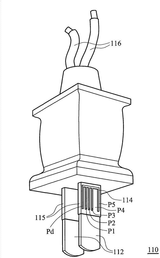
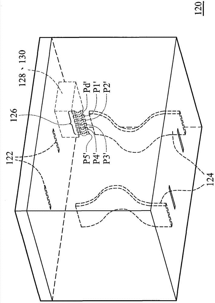
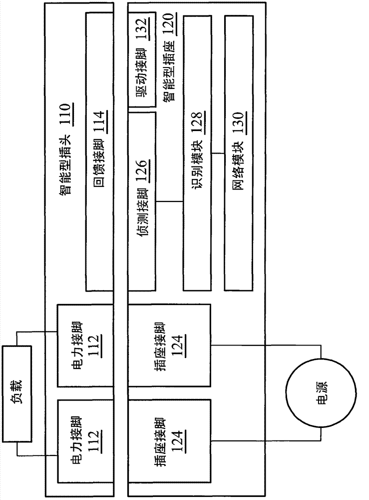
[0062] Figure 2A It is a perspective view of a smart plug according to an embodiment of the present invention (a B-type plug is used here); Figure 2B For the same example with Figure 2A A perspective view of a smart socket matching a smart plug; and Figure 2C for Figure 2A smart plugs with Figure 2B The combined schematic diagram of the smart socket. In this embodiment, the smart plug 210 also includes a set of power pins 212, a cylindrical power ground pin 216 and a set of feedback pins 214, but the set of feedback pins 214 is not as complicated as the previous embodiment. It is only composed of two separate metal layers which are separated by the insulating layer 215 and the power ground pin 216 ground pin. The smart socket 220 also has a set of power jacks 222, a set of socket pins 224, a grounding socket pin 234, a set of detection pins 226, a receiving circuit 232, an identification module 228 and a network module 230 . Same as the previous embodiments, when ...
PUM
 Abstract
Description
Claims
Application Information
 - R&D Engineer
- R&D Manager
- IP Professional
- Industry Leading Data Capabilities
- Powerful AI technology
- Patent DNA Extraction
Browse by: Latest US Patents, China's latest patents, Technical Efficacy Thesaurus, Application Domain, Technology Topic.
© 2024 PatSnap. All rights reserved.Legal|Privacy policy|Modern Slavery Act Transparency Statement|Sitemap