An earphone detection circuit and its detection method

A headphone detection and circuit technology, applied in the direction of electrical components, etc., can solve the problems of high and low levels that are difficult to judge, complex level signals exist at the same time, and achieve the effect of reducing interruption and switching burden, reducing abnormal use, and eliminating false detection

Active Publication Date: 2017-06-06
BYD CO LTD
View PDF5 Cites 0 Cited by
  • Summary
  • Abstract
  • Description
  • Claims
  • Application Information

AI Technical Summary

Problems solved by technology

[0005] The purpose of the present invention is to at least solve one of the above-mentioned technical defects, especially solve the problem that multiple complex level signals exist simultaneously on the first channel circuit, and the high and low levels are difficult to determine, so that any earphone socket can be selected to match the realization of the earphone Purpose of detection

Method used


Image

  • An earphone detection circuit and its detection method
  • An earphone detection circuit and its detection method
  • An earphone detection circuit and its detection method

Examples


Embodiment Construction

[0027] Embodiments of the present invention are described in detail below, examples of which are shown in the drawings, wherein the same or similar reference numerals designate the same or similar elements or elements having the same or similar functions throughout. The embodiments described below by referring to the figures are exemplary only for explaining the present invention and should not be construed as limiting the present invention.

[0028] It should be noted that, in addition, the terms "first" and "second" are only used for descriptive purposes, and cannot be understood as indicating or implying relative importance or implicitly indicating the quantity of indicated technical features. Thus, a feature defined as "first" and "second" may explicitly or implicitly include one or more of these features. Further, in the description of the present invention, unless otherwise specified, "plurality" means two or more.

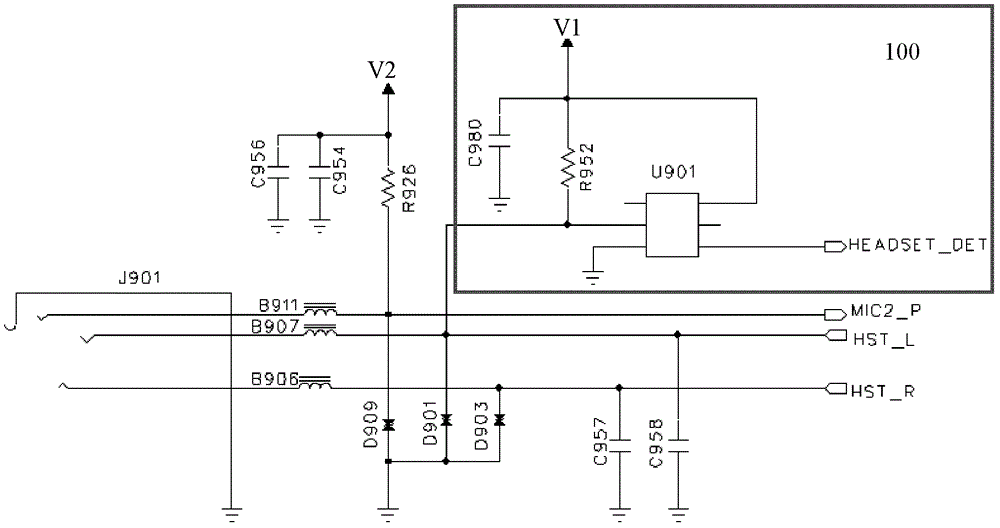
[0029] image 3 Shown is the circuit diagram of the ...


PUM


Abstract

The invention provides a detection circuit and a detection method for an earphone. The detection circuit comprises a microphone signal line, a first sound channel signal line, a second sound channel signal line and a level shaping circuit, wherein the level shaping circuit comprises a first resistor and a schmitt trigger; a first end and a second end of the schmitt trigger are connected with the first resistor; the first end serves as an input end of the level shaping circuit, and is electrically connected with the first sound channel signal line and used for receiving a level signal of a first sound channel; the second end is connected with a power supply network to obtain first voltage to drive the schmitt trigger to operate; and a third end of the schmitt trigger serves as an output end of the level shaping circuit, is electrically connected with an earphone detection pin of a mobile phone master chip and provides a stable high level or a low level for a detection end of the mobile phone master chip. According to the circuit and the method, the wave shaping circuit is arranged at the front end of a sampling circuit of the mobile phone master chip to filter signal oscillation on the first sound channel signal line of the earphone, so that the stable and reliable level is provided for the detection end of the mobile phone master chip.

Description

technical field [0001] The invention relates to the field of earphone detection, in particular to an earphone detection circuit and a detection method thereof. Background technique [0002] Existing electronic devices, such as ultra-thin portable devices such as mobile phones and tablet computers, are all provided with external earphone jacks, ie, earphone holders. A commonly used method for detecting whether an earphone is inserted is to use the mechanical contact and mechanical disconnection between a specific position in the earphone socket and the shrapnel of the earphone to determine whether an earphone is inserted. figure 1 Shown is a schematic diagram of the connection mode of the headphone detection circuit of the existing standard headphone socket, figure 1 The left part is the headphone socket, and the right part is the earphone. The positions M, P, Q, and R of the earphone are respectively connected to the left channel signal line EAR L, the right channel signal...

Claims


Application Information

Patent Timeline
Patent Type & Authority Patents(China)
IPC IPC(8): H04R29/00
Inventor 郑碧珍
Owner BYD CO LTD
Why Eureka
Try Eureka