Valve pot combined slag input method

A technology of slag and slag storage, which is applied in the field of material input and slag input to the high-temperature slag processing device, which can solve the problems of slag condensation, high-temperature blast furnace slag transportation, and difficulty in airtight transportation of high-temperature slag and granular slag. Achieve the effect of continuous work requirements

Inactive Publication Date: 2016-10-26
姜宏泽
View PDF3 Cites 0 Cited by
  • Summary
  • Abstract
  • Description
  • Claims
  • Application Information

AI Technical Summary

Problems solved by technology

[0002] We know that the temperature of steel slag and blast furnace slag is 1400-1650°C, while the melting temperature of pure iron is 1538°C, which means that the temperature of the transported material slag may be higher than the melting temperature of iron, and the problem of blast furnace slag transportation is not only slag The problem of high temperature is mainly the condensation of slag. Therefore, the common material conveying forms of rotary sealing valve type in the market, as well as the material conveying forms of valve type, series and parallel tank type, and large and small bells are difficult to meet the requirements of the new slag processing device. The task of airtightly conveying high-temperature slag and granular slag from low pressure to high pressure, and from high pressure to low pressure
[0003] The existing slag treatment methods such as Inba method, Minte method, Jiaheng method, foam slag method and stuffy slag method do not require closed input and output of slag in the process, so the existing slag treatment devices and methods do not have similar Conveying method and device, the new valve tank combined slag conveying method is mainly a special method designed for the import and export of slag in the patented device of "Steam Circulation Blast Furnace Slag Heat Energy Utilization and Slag Treatment Implementation Device" with application number 200810229364

Method used


Image

  • Valve pot combined slag input method

Examples


Embodiment Construction

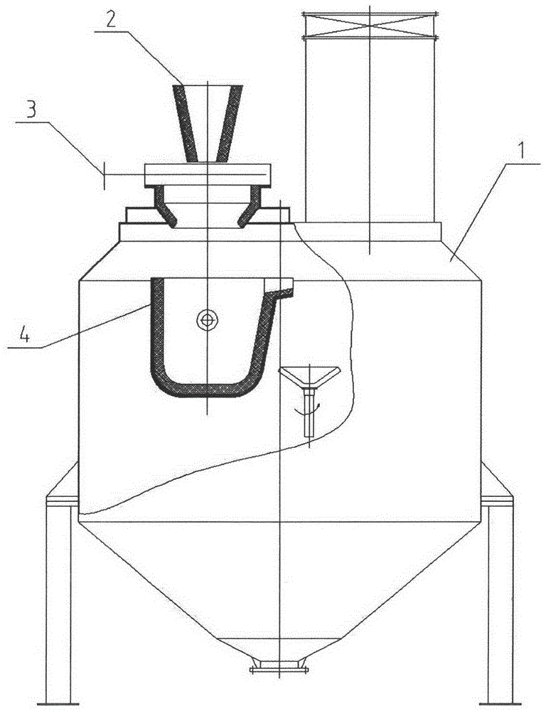
[0020] The present invention will be further described below in conjunction with accompanying drawing:

[0021] The slag treatment device tank of the system should be equipped with more than two tanks according to the needs. Generally, the working system of 3 tanks or 4 tanks is used. In the working mode of 4 tanks, one tank is generally used for slag feeding, one tank for granulation, one tank for slag discharge, and one tank for standby , the working process of each single tank is the same, consisting of slag feeding, granulation, and slag discharging, and more than two single tanks form a continuous slag processing system.

[0022] A single tank works as follows:

[0023] Slag feeding: Open the gate valve, and the slag enters the slag tank along the slag chute. After the slag tank is full, the gate of the slag chute is automatically closed, and it is automatically switched to another slag processing device for slag feeding, and the gate is closed. valve;

[0024] Granulat...


PUM


Abstract

The invention provides a material inputting method, and concretely relates to a method for inputting slag to a high-temperature slag processing device. The method utilizes the high-pressure sealing capability of a valve and the high-temperature slag containing capability of a slag containing tank, adopts the cooperation regime of a valve switch and a tank dumping process, and adopts an alternate work regime of the above two slag processing tanks to realize slag entrance and the continuous work requirements of a system. The method solves a problem that the slag inlet of the slag processing device is difficult to seal, realizes the closed feeding of the metallurgic slag to the slag processing device, and satisfies the high-pressure closed work requirement of the slag processing process of the slag processing device.

Description

technical field [0001] The invention relates to a material input method, in particular to a method for inputting molten slag to a high-temperature molten slag processing device in the technical field of high-temperature molten slag recovery. Background technique [0002] We know that the temperature of steel slag and blast furnace slag is 1400-1650°C, while the melting temperature of pure iron is 1538°C, which means that the temperature of the transported material slag may be higher than the melting temperature of iron, and the problem of blast furnace slag transportation is not only slag The problem of high temperature is mainly the condensation of slag. Therefore, the common material conveying forms of rotary sealing valve type in the market, as well as the material conveying forms of valve type, series and parallel tank type, and large and small bells are difficult to meet the requirements of the new slag processing device. The task of airtightly transporting high-tempera...

Claims


Application Information

Patent Timeline
Patent Type & Authority Patents(China)
IPC IPC(8): C21B3/06C21B3/10
CPCY02W30/50
Inventor 姜宏泽
Owner 姜宏泽
Why Eureka
Try Eureka