
Reclaimer machine

A technology of reclaimer and bucket wheel, which is applied in the direction of earth mover/shovel, open pit mining, earthwork drilling, etc.

Inactive Publication Date: 2013-07-31
VALE LIMITED
View PDF4 Cites 3 Cited by
  • Summary
  • Abstract
  • Description
  • Claims
  • Application Information

AI Technical Summary

Problems solved by technology

This configuration prevents direct access for disassembly and assembly of the components

Method used


Image

  • Reclaimer machine
  • Reclaimer machine
  • Reclaimer machine

Examples


Embodiment Construction

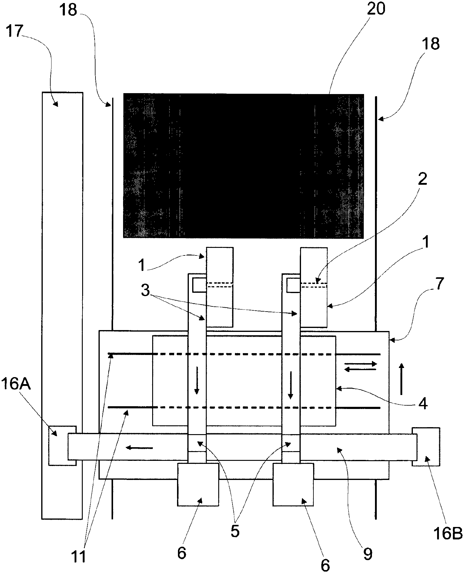
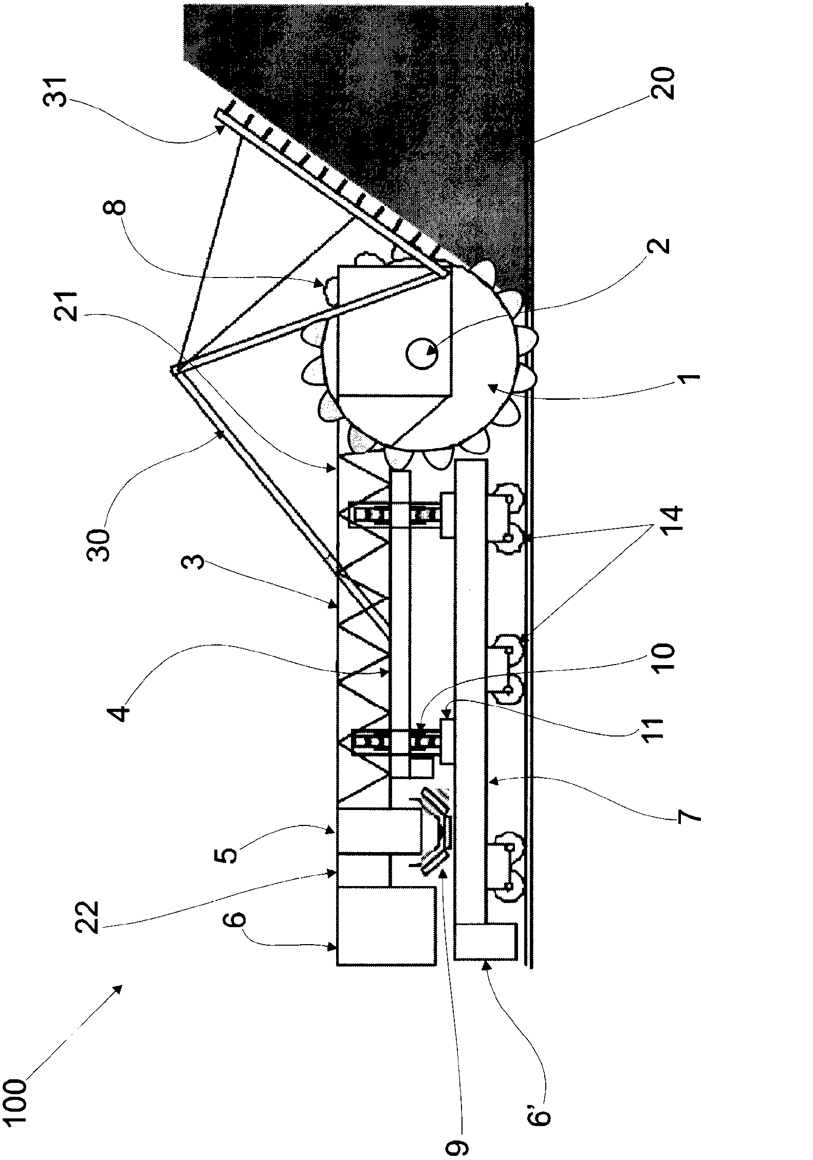
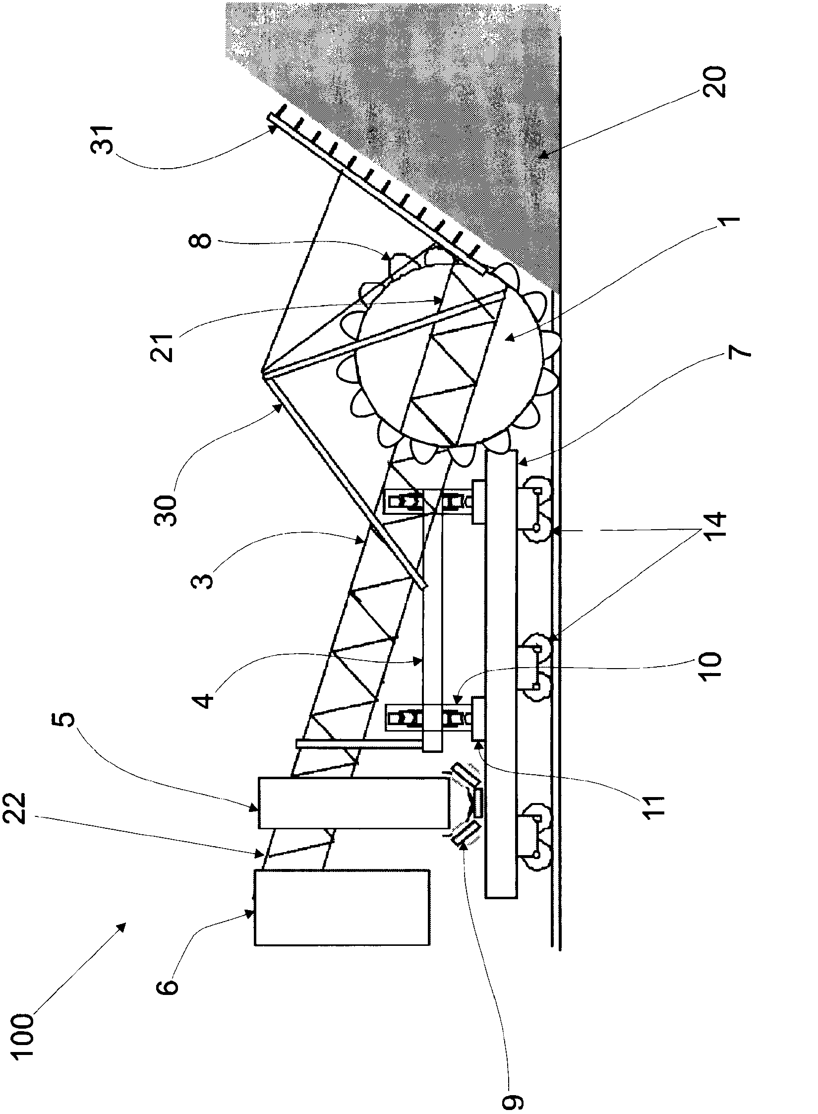
[0017] Based on the preferred embodiment and according to Figure 1 to Figure 3 , the reclaimer 100 includes a bucket wheel 1 that includes a set of buckets 8 rotating around an axis 2 driven by a motor and a reducer (not shown) or by a driving force (torque) such as from a hydraulic motor )drive. The bucket wheel 1 is connected to a conveyor belt structure 3 which supports the bucket wheel 1 and is also connected to a transfer chute 5 .

[0018] The rake support structure 30 is connected to the conveyor belt structure 3 supporting the counterweight 6 . This structure 30 comprises a rake 31 with a breaker directed towards the pile 20 or pile, with the purpose of breaking up the pile 20 . All these structural connections can change according to the calculation and planning development.

[0019] The conveyor structure 3 is supported by an upper platform 4 . The upper platform is placed above at least one and preferably two pairs of wheel sets 10 which move laterally towards ...


PUM


Abstract

This document describes a reclaimer machine (100) for reclaiming and homogenizing materials such as ore, coal and others, stock-piled in yards. The reclaimer machine (100) comprises a bucket wheel (1) which includes a series of buckets (8) rotating about a shaft (2), a conveyor belt (3) connected to the bucket wheel (1) and to a transfer chute (5), the conveyor belt (3) being supported by a mobile upper platform (4) which moves laterally to a pile on tracks attached to a mobile lower platform (7), wherein a first end of the conveyor belt (21) structure is connected to the bucket wheel (1) and another end of the conveyor belt structure (3) is connected to a counterweight (6) which maintains the balance of the reclaimer machine (100) and supports the bucket wheel (1), upper platform (4) and lower platform (7) movements.

Description

technical field [0001] The invention relates to a reclaimer for reclaiming and mixing materials such as ore, coal, etc. stored or piled up in a stockyard. Background technique [0002] The machines currently available for reclaiming and blending material from stacks in storage yards fall into two types: drum reclaimers and bridge reclaimers with bucket wheels. [0003] Bridge reclaimers with wheels and buckets are divided into three components: (a) the feeding system on the stack, (b) the system for the lateral movement of the bucket wheel and rake, and (c) the system for digging and retrieving Steering system for stacked material. The operating dynamics are achieved through the synchrony of the feed, lateral and steering movements of these components. Due to the synchronized movement of these components, the material excavated and retrieved from the stockpile is unloaded in the center of the wheel, where there is a conveyor belt inside the wheel and perpendicular to the s...

Claims


Application Information

Patent Timeline
Patent Type & Authority Applications(China)
IPC IPC(8): E21C47/02
CPCE02F3/181E02F9/18E02F3/188E02F7/06E21C47/02
Inventor 马塞洛·梅内塞斯·克鲁斯
Owner VALE LIMITED
Learn More