Optical Unit with Shake Correction

A shake correction, optical unit technology, applied in the direction of optical components, optical, electrical components, etc., can solve the problems of plastic deformation of spring components, movement obstruction, etc.

Inactive Publication Date: 2016-04-13
SANKYO SEIKI MFG CO LTD
View PDF8 Cites 0 Cited by
  • Summary
  • Abstract
  • Description
  • Claims
  • Application Information

AI Technical Summary

Problems solved by technology

[0008] However, if a spring member is used to support the movable body in a swingable manner, there will be the following problem: when the movable body is displaced in a direction intersecting the optical axis due to an external impact, the spring member will Plastic deformation will occur, which will hinder subsequent actions

Method used


Image

  • Optical Unit with Shake Correction
  • Optical Unit with Shake Correction
  • Optical Unit with Shake Correction

Examples


Embodiment Construction

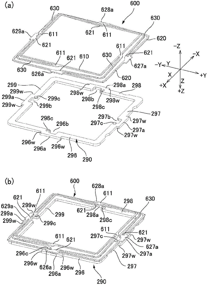
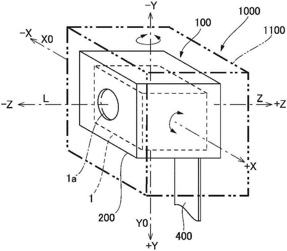
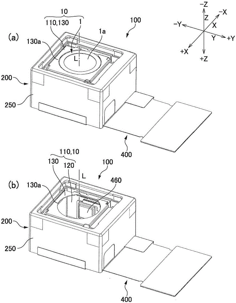
[0069] Hereinafter, preferred modes for implementing the present invention will be described with reference to the drawings. In addition, in the following description, the structure for preventing a hand shake of an imaging means is shown as an example. In addition, in the following description, let three directions orthogonal to each other be X-axis, Y-axis, and Z-axis, respectively, and let the direction along optical axis L (lens optical axis) be Z-axis. In addition, in the following description, among the shakes in each direction, the rotation around the X axis corresponds to the so-called pitch (longitudinal shake), the rotation around the Y axis corresponds to the so-called yaw (lateral shake), and the rotation around the Z axis corresponds to the so-called pitch (longitudinal shake). to the so-called side roll. In addition, mark +X on one side of the X-axis, -X on the other side, +Y on one side of the Y-axis, -Y on the other side, and The opposite side / rear side in th...


PUM


Abstract

The present invention provides an optical unit with a shake correction function, which can prevent the plastic deformation of the spring member even when the movable body and the fixed body are connected by the spring member. In the optical unit (100) with shake correction function, when the movable body (10) holding the lens etc. is supported in a swingable manner, the spring member (600) is connected with the movable body (10) (200) connect. In addition, between the spring member (600) in the optical axis direction and the swing fulcrum (180) of the movable body (10), the spring member (290) is fixed to the inner peripheral surface of the fixed body (200), thereby limiting the possible The amount of displacement of the movable body (10) in the direction crossing the optical axis due to external impact.

Description

technical field [0001] The present invention relates to an optical unit with a shake correction function mounted in a mobile phone with a camera or the like. Background technique [0002] In recent years, mobile phones have been configured as optical devices equipped with an optical unit for photographing. The optical unit for photographing includes a movable body including a lens, a focusing lens drive mechanism for magnetically driving the movable body in the direction of an optical axis, and an imaging unit in which an imaging element is supported on a support. In the related optical unit, in order to suppress the disorder of the photographed image caused by the hand shake of the user, it is proposed that the photographing unit is constituted as a movable body that can swing on a fixed body, and that the photographing unit (movable body) and the A structure in which a shake correction drive mechanism is provided between the fixed bodies. In addition, when the imaging un...

Claims


Application Information

Patent Timeline
Patent Type & Authority Patents(China)
IPC IPC(8): G03B5/00H04N5/225
CPCG03B5/00G03B2205/0069G03B2205/0007G02B27/64
Inventor 武居勇一滨田吉博柳泽克重
Owner SANKYO SEIKI MFG CO LTD
Why Eureka
Try Eureka