

Expandable parking device for planet entering prober experiments
A technology for access devices and experiments, which can be applied to workbenches, manufacturing tools, etc., and can solve problems such as waste of parking devices
- Summary
- Abstract
- Description
- Claims
- Application Information
AI Technical Summary
Problems solved by technology
Method used
Image

Examples
Embodiment 1
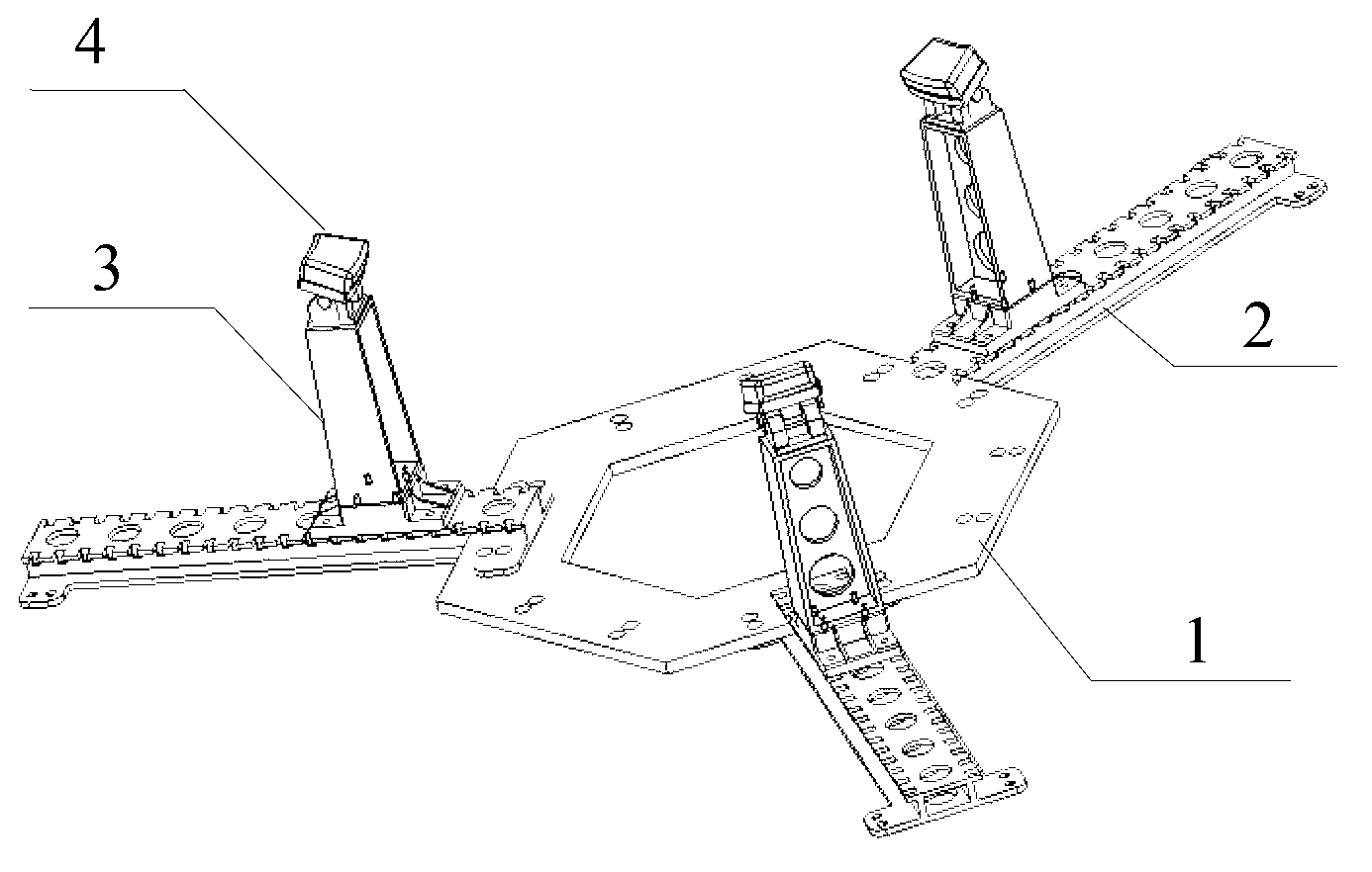
[0020] Such as figure 1 As shown, the parking device applied to the small-scale planetary enterer provided by the present invention is composed of a flange 1 , a guide rail 2 , a bracket 3 , and a foot 4 .
[0021] The flange 1 is a hexagonal flange, and flanges of other shapes can also be used as required. Three guide rails 2, three supports 3 and three legs 4 are installed when the hexagonal flange 1 is parked on a small-scale planetary feeder. One end of the three guide rails 2 is fixedly connected to the flange plate 1 by four bolts, and is evenly distributed around the flange plate 1 at 120°. The symmetrical positions on both sides of the guide rails 2 are spaced by 0.1 meters to open positioning holes for the support 3. An installation interface is provided; the lower end of the bracket 3 is vertically installed on the end of the guide rail 2 close to the flange 1 through 4 bolts, and the upper end of the bracket 3 is connected to the leg 4 . Such as image 3 As shown...
Embodiment 2
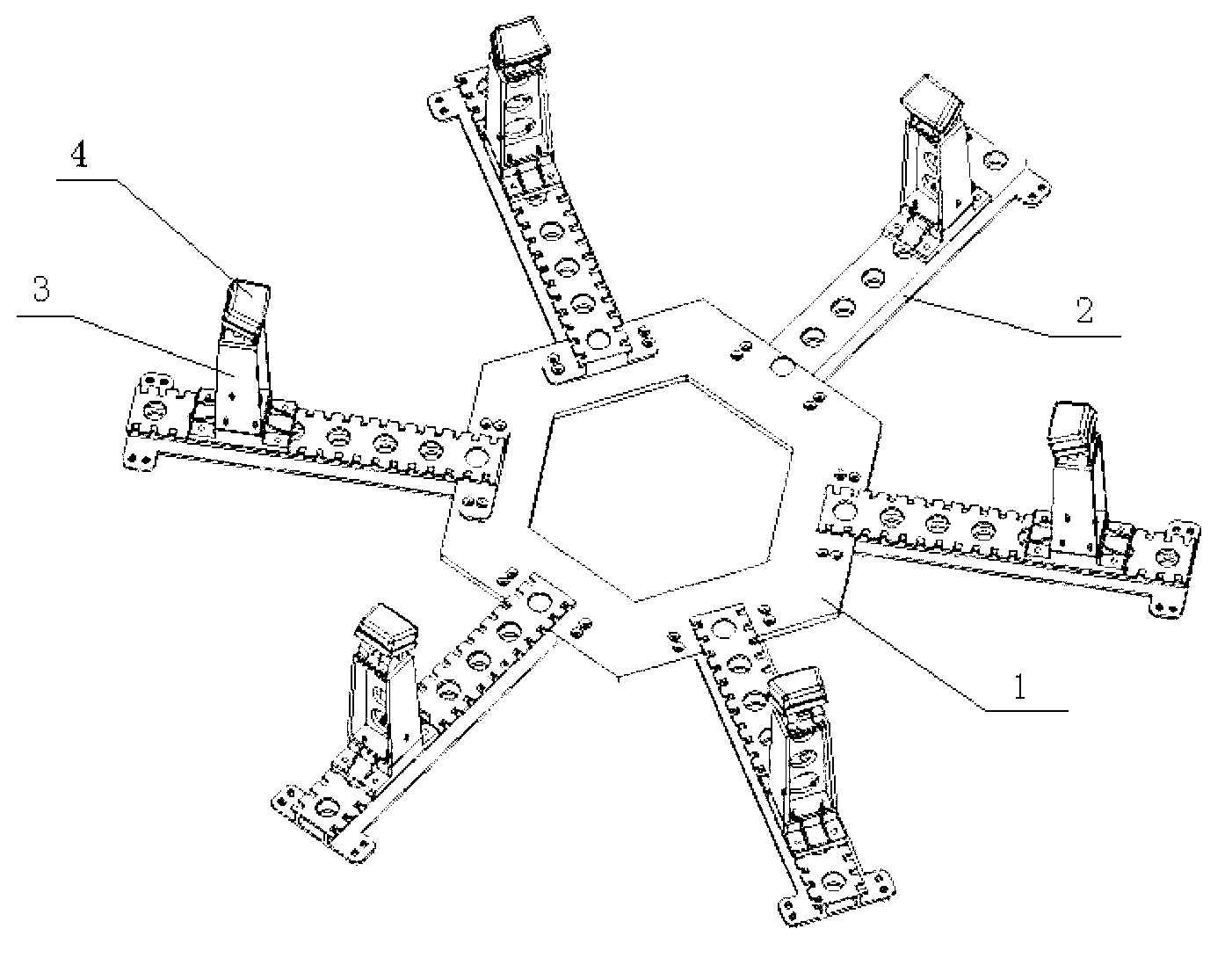
[0023] Such as figure 2 As shown, the parking device applied to a large-scale planetary enterer provided by the present invention is composed of a flange 1 , a guide rail 2 , a bracket 3 , and a foot 4 .
[0024] The flange plate 1 is a hexagonal flange, and six guide rails 2, six brackets 3 and six legs 4 are installed when the large-scale planetary enterer is parked. One end of the six guide rails 2 is fixedly connected to the flange 1 by 4 bolts, and is evenly distributed around the flange 1 at 60°. The symmetrical positions on both sides of the guide rail 2 are opened with positioning holes at intervals of 0.1 m for the support 3. An installation interface is provided; the lower end of the bracket 3 is vertically installed on the end of the guide rail 2 away from the flange 1 through four bolts, and the upper end of the bracket 3 is connected to the foot 4 . Such as image 3 The self-adaptive foot 4 shown is installed on the bracket 3, and the pitch direction is adjusta...
PUM
 Abstract
Description
Claims
Application Information