Test tube cover collection mechanism

A collection mechanism and test tube cover technology, applied in the field of medical devices, can solve the problems of low efficiency, complicated structure and operation, and achieve the effect of reliable recovery operation and simple structure

Inactive Publication Date: 2014-12-03
无锡特可思衡机贸易有限公司
View PDF6 Cites 0 Cited by
  • Summary
  • Abstract
  • Description
  • Claims
  • Application Information

AI Technical Summary

Problems solved by technology

[0002] After the collection of samples such as blood is completed, the test and analysis equipment must be used to detect and analyze the samples in the test tube. The sample needs to be opened before entering the test and analysis instrument. Among them, the manual opening method is inefficient and has potential hazards of contamination such as laboratory-acquired infection, while the automatic machine opening method has the characteristics of high efficiency and no pollution. Automatic machine opening is usually used The test tube body clamp clamps the test tube and then removes the test tube cover using the capping mechanism to complete. Usually, a single test tube is uncapped. Some equipment can also perform capping operations on multiple test tubes at the same time. The test tube with the test tube cover removed is Transported to the next operation equipment, and the removed test tube caps are usually collected manually, or through some guiding devices, the test tube caps are guided and automatically fall into the recycling box, as disclosed in Chinese patent ZL200810003168.2. Automatic test tube cap removal device", after the test tube cap is removed, the cap clamp is separated, the cap holding pin is pressed against the top surface of the cap through the cylinder action, and the coil spring on the cap holding pin is compressed by the cylinder action, at this time Use the removal mechanism to remove the test tube cap, and then through the pushing action of the coil spring, the test tube cap will fall freely under the guidance of the guide and fall into the recovery box below. The recovery device is for each test tube. Each cap needs to be equipped with a corresponding test tube cap clamping mechanism, cap clamping pin, coil spring and guide, and the structure and operation are complicated.

Method used


Image

  • Test tube cover collection mechanism
  • Test tube cover collection mechanism
  • Test tube cover collection mechanism

Examples


Embodiment Construction

[0018] The specific implementation manner of the present invention will be described below in conjunction with the accompanying drawings.

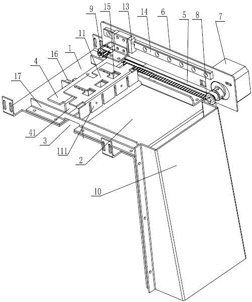
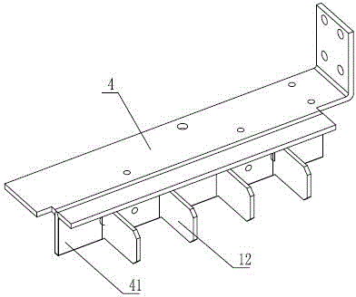
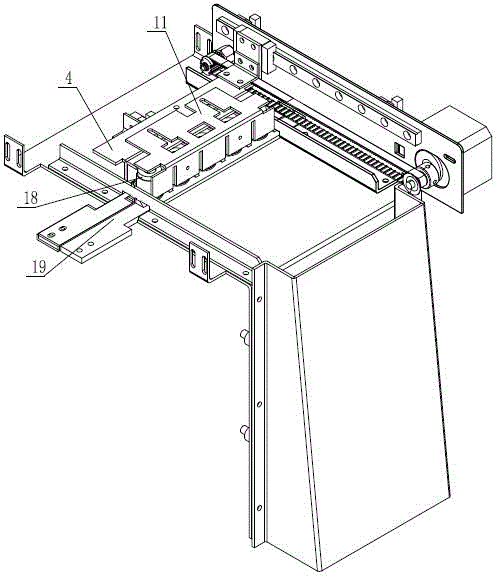
[0019] See figure 1 , figure 2 , the present invention comprises connecting plate one 1 and connecting plate two 2, leave transverse gap 3 between connecting plate one 1 and connecting plate two 2, the top of transverse gap 3 is provided with push plate 4, and push plate 4 is fixed with conveyor belt 5 Then, the mounting plate 6 is longitudinally fixed on the connecting plate one 1 and the connecting plate two 2, the motor 7 is fixed on the mounting plate 6, the output shaft of the motor 7 is connected with the main pulley 8, and the main pulley 8 is connected with the mounting plate 6. The other end is wound with a transmission belt 5 from the pulley 9; the side of the connecting plate 2 is provided with a recycling box 10; The plate 11 has a vertical arm 2 111. The push plate 4 and the cover plate 11 form a covering space with an open...


PUM


Abstract

A test tube cover collection mechanism comprises a first connecting board and a second connecting board. A transverse gap is formed between the first connecting board and the second connecting board. A push board is arranged above the transverse gap and fixedly connected with a conveyer belt. A mounting board is longitudinally fixed on the first connecting board and the second connecting board. A motor is fixed on the mounting board. An output shaft of the motor is in transmission connection with a main pulley. The conveyer belt is connected to the main pulley and an auxiliary pulley at the other end of the mounting board in a wound manner. A recovery box is arranged on the side of the second connecting board. The push board is fixedly connected with a cover board and is provided with a first vertical arm. The cover board is provided with a second vertical arm. The push board and the cover board form a covering space with a downward opening. The covering space is located right above the transverse gap and used for accommodating test tube covers removed. The test tube cover collection mechanism is available for recovering test tube covers removed from test tubes in batches, capable of preventing the test tube covers from moving out during cover removal, and simple in structure.

Description

technical field [0001] The invention relates to the technical field of medical instruments, in particular to an auxiliary device of a test tube cap removal device, which is used for collecting removed test tube caps. Background technique [0002] After the collection of samples such as blood is completed, the test and analysis equipment must be used to detect and analyze the samples in the test tube. The sample needs to be opened before entering the test and analysis instrument. Among them, the manual opening method is inefficient and has potential hazards of contamination such as laboratory-acquired infection, while the automatic machine opening method has the characteristics of high efficiency and no pollution. Automatic machine opening is usually used The test tube body clamp clamps the test tube and then removes the test tube cover using the capping mechanism to complete. Usually, a single test tube is uncapped. Some equipment can also perform capping operations on multi...

Claims


Application Information

Patent Timeline
Patent Type & Authority Patents(China)
IPC IPC(8): B67B7/14
Inventor 施洪明倪冬亚
Owner 无锡特可思衡机贸易有限公司
Why Eureka
Try Eureka