Eureka AIR delivers breakthrough ideas for toughest innovation challenges, trusted by R&D personnel around the world.

Sealing device

A technology of sealing device and sealing ring, which is applied in the direction of engine sealing, engine components, mechanical equipment, etc., can solve the problems of liquid penetration, gas leakage in pneumatic diaphragm pumps, etc., and achieve the effect of improving sealing and confidentiality performance

Inactive Publication Date: 2013-09-11
苏州铭牌机械科技有限公司
View PDF0 Cites 0 Cited by
  • Summary
  • Abstract
  • Description
  • Claims
  • Application Information

AI Technical Summary

Problems solved by technology

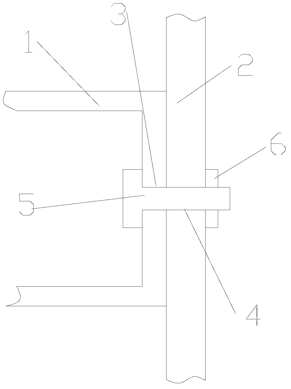
[0002] Existing technology as attached figure 1 The connection between the central body 1 and the air chamber end cover 2 is also fixed by the cooperation between the bolt 5 and the bolt 6. Since the air flow exists in the central body 1 and the air chamber end cover 2, the bolt 5 and the central body There is inevitably a gap between the first through hole 3 in 1 and the second through hole 4 in the air chamber end cover 2, so that the gas in the pneumatic diaphragm pump leaks and forms a flow, which in turn makes the transported liquid permeate

Method used


Image

  • Sealing device
  • Sealing device

Examples


Embodiment Construction

[0012] The present invention is described below in conjunction with accompanying drawing.

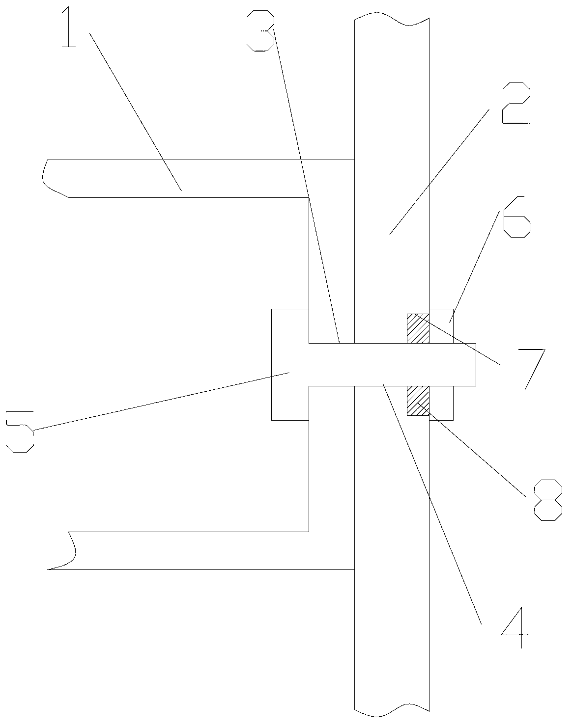
[0013] attached figure 2 It is a sealing device according to the present invention, which includes a central body 1 and an air chamber end cover 2, the central body 1 and the air chamber end cover 2 respectively have a first through hole 3 and a second through hole 4, and bolts 5 It is connected and fixed with the nut 6; the air chamber end cover 2 is provided with a groove 7 at the position of the second through hole 4, and a sealing ring 8 is arranged in the groove 7.

[0014] Wherein the groove 7 is arranged on the side of the air chamber end cover 2 away from the central body 1 . .

[0015] During the use of the sealing device of the present invention, the seal ring 8 provided in the groove 7 is completely sealed between the bolt 5 and the end cover 2 of the air chamber, which effectively improves the sealing between the central body 1 and the end cover of the air chamber. The t...


PUM


Abstract

The invention discloses a sealing device which comprises a central body and an air chamber end cap. The central body and the air chamber end cap are provided with a first through hole and a second through hole respectively and fixed through a bolt and a nut connectedly, the air chamber end cap is provided with a groove at the position of the second through hole, and a sealing ring is arranged in the groove. When the sealing device is in use, space between the bolt and the air chamber end cap is completely sealed by the sealing ring arranged in the groove, so that sealability of connected fixing between the central body and the air chamber end cap is effectively improved and sealability of a pneumatic diaphragm pump is improved.

Description

technical field [0001] The invention relates to a sealing device used on a pneumatic diaphragm pump. Background technique [0002] Existing technology as attached figure 1 The connection between the central body 1 and the air chamber end cover 2 is also fixed by the cooperation between the bolt 5 and the bolt 6. Since the air flow exists in the central body 1 and the air chamber end cover 2, the bolt 5 and the central body There is inevitably a gap between the first through hole 3 in 1 and the second through hole 4 in the air chamber end cover 2, so that the gas in the pneumatic diaphragm pump leaks and forms a flow, which in turn makes the transported liquid permeate . Contents of the invention [0003] In view of the above-mentioned existing technical problems, the object of the present invention is to propose a sealing device. [0004] The technical solution of the present invention is achieved as follows: a sealing device, including a central body and an air chamber...

Claims


Application Information

Patent Timeline
IPC IPC(8): F16J15/06
Inventor 陆香春
Owner 苏州铭牌机械科技有限公司
Why Eureka
Eureka Blog
Learn More