

Motor vehicle stream-oriented intersection traffic pre-signal control method
A technology of intersection and signal control, applied in the direction of controlling traffic signals, etc., can solve problems such as the decrease of traffic capacity at intersections, the adjustment of the timing scheme of pre-signals and main signals, and motor vehicle congestion.
- Summary
- Abstract
- Description
- Claims
- Application Information
AI Technical Summary
Problems solved by technology
Method used
Image

Examples
specific Embodiment approach 1
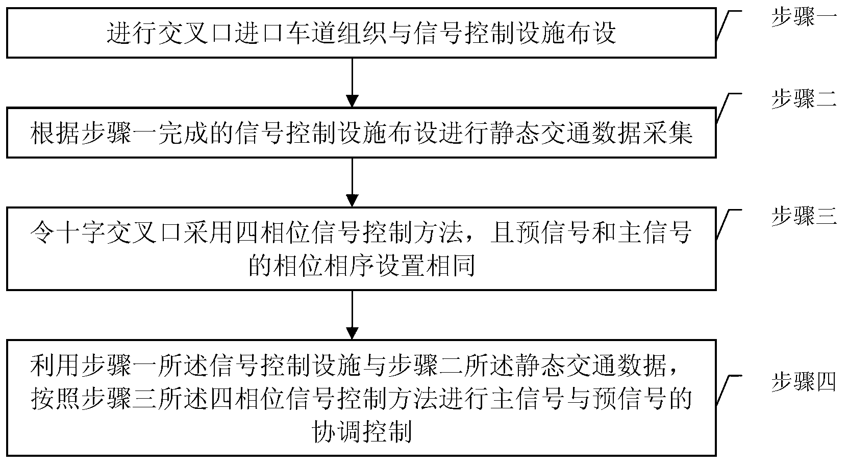
[0020] Specific implementation mode 1. Combination Figure 1-Figure 3 This specific embodiment will be described. A traffic pre-signal control method at a crossing oriented to motor vehicle flow, comprising the steps of:
[0021] Step 1: Carry out the organization of intersection entrance lanes and the layout of signal control facilities;
[0022] Step 2: Collect static traffic data according to the layout of signal control facilities completed in Step 1;
[0023] The static traffic data includes the width of each lane of the intersection, the saturated traffic flow rate of each entrance lane of the intersection and the green light loss time of each phase of the intersection;
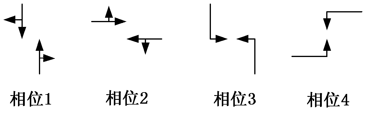
[0024] Step 3: Make the intersection adopt the four-phase signal control method, and the phase sequence of the pre-signal and the main signal are set to be the same;
[0025] Step 4: Using the signal control facilities described in step 1 and the static traffic data described in step 2, the coordinat...
specific Embodiment approach 2
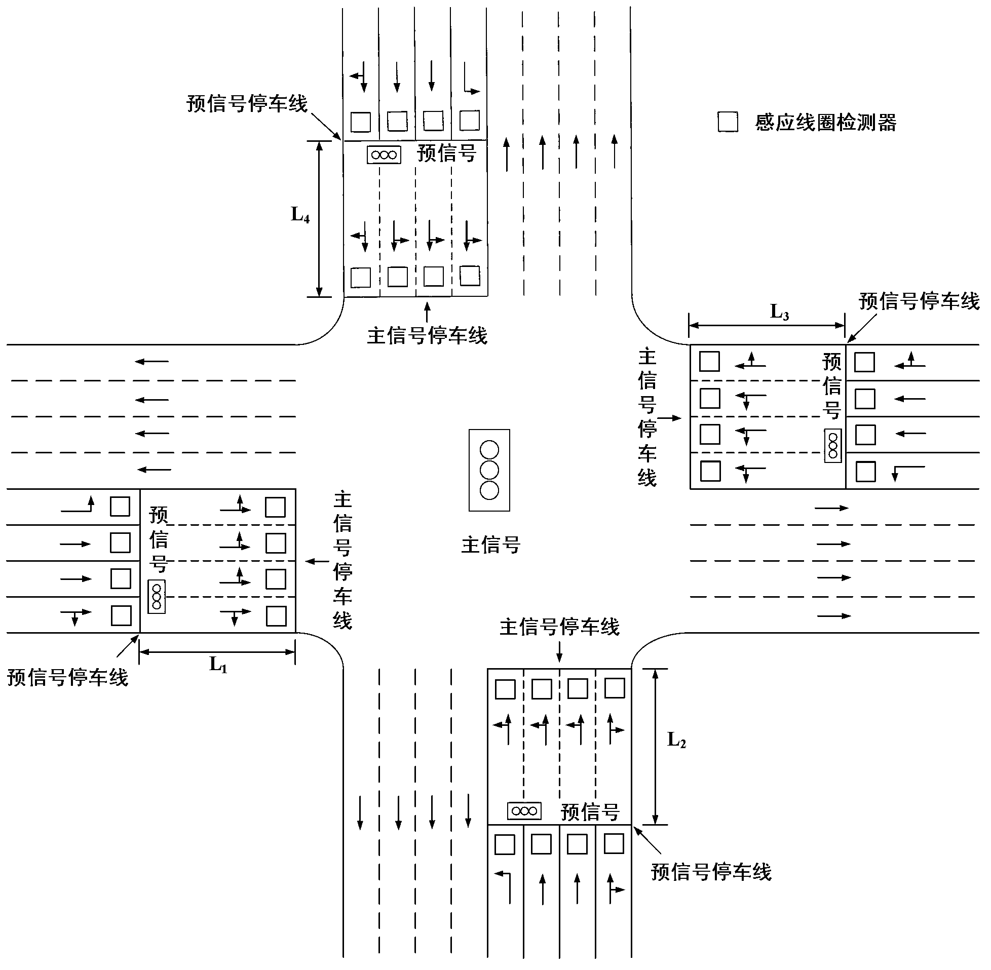
[0026] Embodiment 2. The difference between this embodiment and embodiment 1 is that step 1: the process of organizing the intersection entrance lane organization and laying out signal control facilities is as follows:
[0027] Step 1A: Determine the length of the waiting area for each entrance direction of the intersection; the waiting area is the area between the main signal stop line and the pre-signal stop line;
[0028] The length L of the waiting area in the direction of the i-th entrance i for:
[0029] L i =1.2×L imax +20
[0030] Unit: m, where:
[0031] L i max = max ( C 0 × q ‾ il , C 0 × q ‾ is ...
specific Embodiment approach 3
[0045] Specific embodiment three, combine Figure 4 This specific embodiment will be described. The difference between this embodiment and the second embodiment is the fourth step: using the signal control facility described in step one and the static traffic data described in step two, the main signal and the pre-signal are performed according to the four-phase signal control method described in step three The process of coordinated control is:
[0046] Step 4A: Clear the initial data of the induction coil detector;
[0047] Step 4B: The main signal is turned on in sequence according to the preset phase sequence, and the pre-signal is turned on according to the sequence of the main signal;
[0048] The corresponding relationship of the green light phase is: when the green light of the i-th phase of the main signal starts to light up, the i-th phase and the j-th phase green light of the pre-signal start to light up synchronously;
[0049] j = mod(i+1, 4)+1
[0050] i=mod(i...
PUM
 Abstract
Description
Claims
Application Information