A monitoring system and an alarm linkage method

A monitoring system and linkage technology, applied in the monitoring field, can solve the problem of a small number of alarm events and achieve high feasibility

Active Publication Date: 2016-12-28
EMERSON NETWORK POWER CO LTD
View PDF6 Cites 0 Cited by
  • Summary
  • Abstract
  • Description
  • Claims
  • Application Information

AI Technical Summary

Problems solved by technology

[0005] Embodiments of the present invention provide a monitoring system and an alarm linkage method to solve the problem in the prior art that the number of alarm events capable of alarm linkage is small

Method used


Image

  • A monitoring system and an alarm linkage method
  • A monitoring system and an alarm linkage method
  • A monitoring system and an alarm linkage method

Examples


Embodiment 1

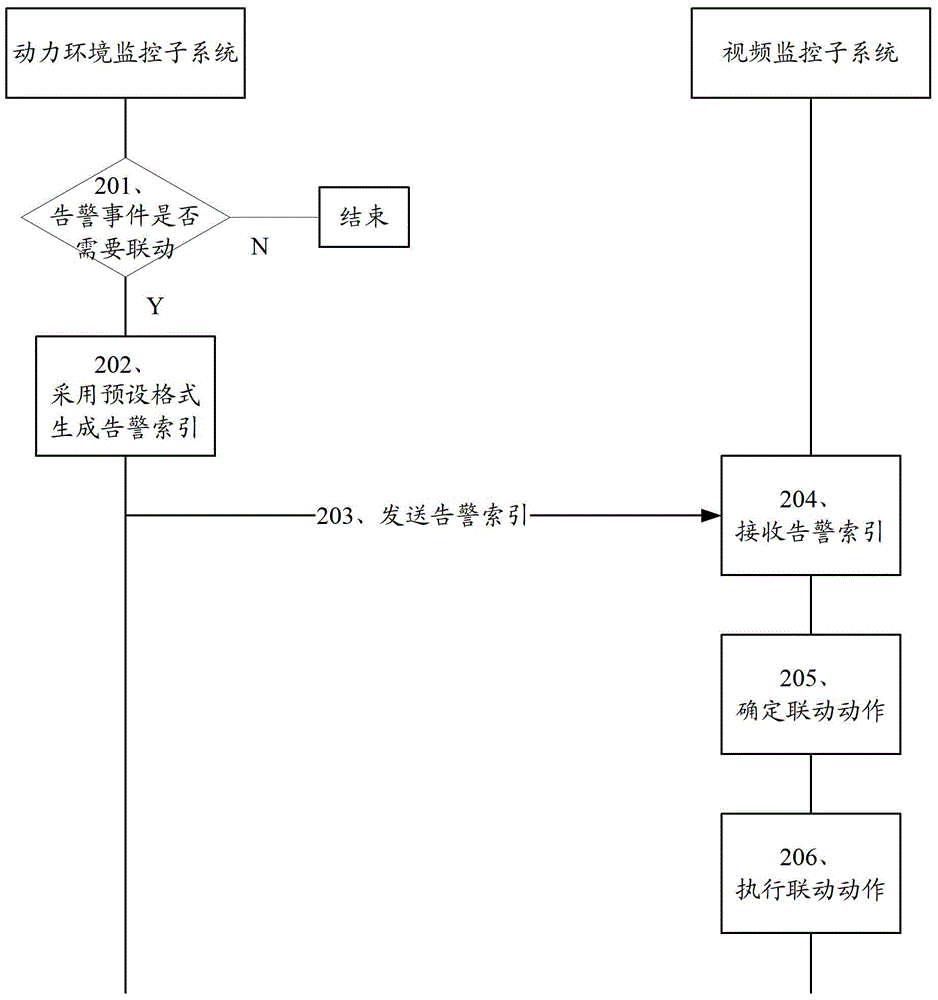
[0033] figure 2 Shown is the detailed flow of the alarm linkage method provided by Embodiment 1 of the present invention, which specifically includes the following processing steps:

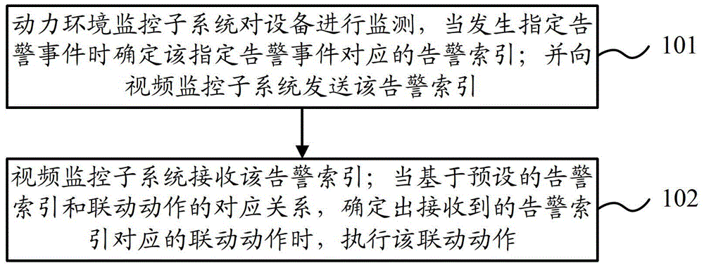
[0034] Step 201, the power environment monitoring subsystem monitors the equipment, and determines whether the alarm event of the monitored equipment is an alarm event requiring alarm linkage.

[0035] When the power environment monitoring subsystem determines that the alarm event of the monitored equipment is an alarm event that requires alarm linkage, enter step 202; when the power environment monitoring subsystem determines that the alarm event of the monitored equipment does not require alarm linkage When the alarm event occurs, the process ends.

[0036] Step 202, using a preset format to generate an alarm index corresponding to an alarm event requiring alarm linkage.

[0037] The preset format can be customized by the user. For example, in Embodiment 1 of the present invention, the follo...

Embodiment 2

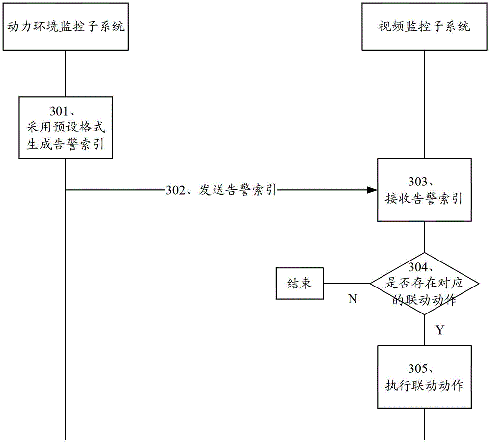
[0054] image 3 Shown is the detailed flow of the alarm linkage method provided by Embodiment 2 of the present invention, which specifically includes the following processing steps:

[0055] Step 301 , the power environment monitoring subsystem monitors the equipment, and when any alarm event occurs on the monitored equipment, an alarm index corresponding to any alarm event is generated in a preset format.

[0056] For the specific method of generating the alarm index, reference may be made to step 202 in the above-mentioned embodiment 1, which will not be repeated here.

[0057] Step 302, the power environment monitoring subsystem sends the alarm index to the video monitoring subsystem.

[0058] Step 303, the video monitoring subsystem receives the alarm index sent by the power environment monitoring subsystem.

[0059] Step 304, the video monitoring subsystem determines whether there is a corresponding linkage action in the received alarm index based on the preset correspo...

Embodiment 3

[0066] Figure 4 Shown is the detailed flow of the alarm linkage method provided by Embodiment 3 of the present invention, which specifically includes the following processing steps:

[0067] Step 401, the power environment monitoring subsystem monitors the equipment, and based on the preset correspondence between alarm events and alarm indexes, determines the alarm index corresponding to the alarm event that needs to be linked with the alarm that occurs on the monitored equipment.

[0068] The preset corresponding relationship between alarm events and alarm indexes is the corresponding relationship between alarm events requiring alarm linkage and alarm indexes.

[0069] That is, to adopt the solution of Embodiment 3 of the present invention, it is necessary to predetermine the alarm index corresponding to the alarm event requiring alarm linkage, and pre-store the corresponding relationship between the alarm event requiring alarm linkage and the alarm index in the power enviro...


PUM


Abstract

The invention discloses a monitoring system and an alarm linkage method. The monitoring system comprises a power environment monitoring subsystem and a video monitoring subsystem, wherein the power environment monitoring subsystem is used for monitoring equipment, determining an alarm index corresponding to a specified alarm event when the specified alarm event occurs to the monitored equipment, and sending the alarm index to the video monitoring subsystem; the video monitoring subsystem receives the alarm index sent by the power environment monitoring subsystem, executes a linkage action when the linkage action corresponding to the received alarm index is determined on the basis of a preset corresponding relation of the alarm index and the linkage actions, and records a video of the equipment with the specified alarm event. By the monitoring system and the alarm linkage method, the problem that a small number of alarm events can be used for performing alarm linkage in the prior art is solved.

Description

technical field [0001] The invention relates to the technical field of monitoring, in particular to a monitoring system and an alarm linkage method. Background technique [0002] At present, more and more monitoring systems of base stations and computer rooms use both the power environment monitoring subsystem and the video monitoring subsystem. The power environment monitoring subsystem is mainly used to monitor the Dynamic scenes in the base station and equipment room. In many cases, users hope that the alarm linkage between the power environment monitoring subsystem and the video monitoring subsystem can be realized, that is, when the power environment monitoring subsystem alarms, the video monitoring subsystem can perform linkage actions. For example, when the power environment monitoring subsystem monitors that a smart device is damaged and issues an alarm, the video monitoring subsystem can start video monitoring the damaged smart device. [0003] In the prior art, t...

Claims


Application Information

Patent Timeline
Patent Type & Authority Patents(China)
IPC IPC(8): H04N7/18
Inventor 黎春玲王冬
Owner EMERSON NETWORK POWER CO LTD
Why Eureka
Try Eureka