Adjustable multi-band antenna system

A multi-frequency antenna and adjustable technology, which is applied to antennas, antenna supports/installation devices, and devices that make antennas work in different frequency bands at the same time, which can solve the problems of small antenna space, small mobile phone antenna space, and complex antenna environment. , to achieve the effect of multiple frequency bands and wide bandwidth

Inactive Publication Date: 2013-09-25
SHANGHAI AMPHENOL AIRWAVE COMM ELECTRONICS CO LTD
View PDF8 Cites 61 Cited by
  • Summary
  • Abstract
  • Description
  • Claims
  • Application Information

AI Technical Summary

Problems solved by technology

In addition, due to the complexity of functions such as mobile phone terminals, the space for mobile phone antennas is getting smaller and smaller. Therefore, based on the premise of being responsible for the small space in the environment, debugging an antenna covering the frequency bands of 704-960Mhz and 1710-2700Mhz also brings challenges to the antenna design. difficulty
[0003] In addition, portable terminal products with metal texture are favored by consumers, but too man

Method used


Image

  • Adjustable multi-band antenna system
  • Adjustable multi-band antenna system
  • Adjustable multi-band antenna system

Examples


Embodiment 1

[0031] An adjustable multi-frequency antenna system suitable for mobile terminals with a metal frame structure. The antenna system includes a metal frame, a PCB board and an antenna part; the PCB board is a general printed circuit board (Printed circuit board).

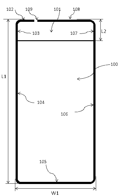
[0032] Such as figure 1 As shown, the metal frame includes a first bottom frame 102, a first side frame 103, a second side frame 104, a top frame 105, a third side frame 106, a fourth side frame 107, and a second bottom frame 108; 102. The first side frame 103, the second side frame 104, the top frame 105, the third side frame 106, the fourth side frame 107 and the second bottom frame 108 are connected in sequence to form a first space; the first bottom frame 102 and A gap 109 is provided between the second bottom frame 108; the metal frame is wrapped around the mobile terminal; the first bottom frame 102 and the second bottom frame 108 correspond to the bottom of the mobile terminal. In this embodiment, taking a general...

Embodiment 2

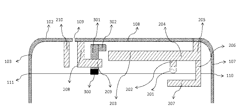
[0053] Such as Image 6 As shown, the difference between this embodiment and Embodiment 1 is that the antenna part is not provided with the first high-frequency coupling arm 210. This embodiment 1 is suitable for the first bottom frame 102 and the first side frame 103. Frequency parasitic arm demand situation. The other technical features of this embodiment are the same as those of Embodiment 1, and will not be repeated here.

Embodiment 3

[0055] Such as Figure 7 As shown, the difference between this embodiment and Embodiment 1 is that the antenna part includes a second high-frequency coupling arm 212 and a second coupling location 211, which replaces the first high-frequency coupling arm 210 in Embodiment 1. The second high-frequency coupling arm 212 is arranged in the same plane as the feeder trace, and the second coupling point 211 is arranged in the PCB board; the second high-frequency coupling arm 212 is connected to the second coupling point 211 and is connected to The second low frequency branch 204 corresponds to it. The second high-frequency coupling arm 212 in this embodiment serves as a high-frequency parasitic arm for generating required high-frequency resonance. The other technical features of this embodiment are the same as those of Embodiment 1, and will not be repeated here.


PUM


Abstract

The invention discloses an adjustable multi-band antenna system which is suitable for mobile terminals with metal frame structures. The adjustable multi-band antenna system comprises a metal frame, a PCB and an antenna part. According to the adjustable multi-band antenna system, the metal frame is designed as one part of an aerial radiation body, a clearance is formed in the metal frame, a low-frequency branch is arranged to be combined with the metal frame to generate low-frequency resonance oscillation, and a high-frequency branch is arranged for generating high-frequency resonance oscillation. An IFA mode is adopted by the adjustable multi-band antenna system, the metal frame is used for achieving the ground point supporting section of the IFA antenna, and a low-frequency coupling part and a high-frequency coupling part can be added additionally according to needs. The adjustable multi-band antenna system has the advantages that the clearance of the metal frame is formed in the bottom, the collision on the clearance can be avoided to the greatest extent in an actual using process of a user, and the phenomenon that when the antenna is held by the hand performance is poor is avoided. The working frequency band of the adjustable multi-band antenna system is 704Mhz to 960Mhz and 1710Mhz to 2700Mhz, and multiple frequency broadband can be achieved. Compared with a traditional general antenna, the adjustable multi-band antenna system has the advantages of being multiple in frequency band and wide in bandwidth.

Description

Technical field [0001] The invention belongs to the field of antenna technology, and specifically relates to an adjustable multi-frequency antenna system. Background technique [0002] The antenna multi-frequency broadband of mobile terminals has always been the development direction of mobile communications, especially portable mobile terminals. Universal Mobile Telecommunications System (UMTS) has become the current mainstream, and its frequency bandwidth is 824Mhz-960Mhz and 1710Mhz-2170Mhz . On the other hand, with the application of LTE technology, in addition to the above frequency bands, LTE700MHZ is also included, so the low frequency bandwidth is 700Mhz-960Mhz. Some also include high frequency bands LTE2.3GHZ and LTE2.5GHZ, so the high frequency bandwidth is 2500Mhz-2700Mhz. In addition, due to the complexity of mobile phone terminals and other functions, the space of mobile phone antennas is getting smaller and smaller, so based on the premise of being responsible for...

Claims


Application Information

Patent Timeline
IPC IPC(8): H01Q5/00H01Q1/24H01Q5/10H01Q5/28H01Q5/307H01Q5/385H01Q5/392
Inventor 董孩李
Owner SHANGHAI AMPHENOL AIRWAVE COMM ELECTRONICS CO LTD
Why Eureka
Try Eureka