Visual target plate device for calibrating component mounting attitude and calibration method

A calibration method and visual technology, applied in the field of visual measurement, can solve problems such as difficulty in ensuring accuracy, inability to realize digital real-time tracking measurement and calibration, and inability to adapt to technological development trends.

Active Publication Date: 2013-10-02
SHANXI ZHIDIAN TECH CO LTD
View PDF8 Cites 29 Cited by
  • Summary
  • Abstract
  • Description
  • Claims
  • Application Information

AI Technical Summary

Problems solved by technology

This method cannot realize digital real-time tracking measurement and calibration. It is not only time-consuming and laborious for the staff to operate, but also the accuracy is difficult to guarantee. It has been unable to adapt to the technological development trend of modern combat aircraft manufacturing.

Method used


Image

  • Visual target plate device for calibrating component mounting attitude and calibration method
  • Visual target plate device for calibrating component mounting attitude and calibration method
  • Visual target plate device for calibrating component mounting attitude and calibration method

Examples


Embodiment

[0078] The camera imaging system used in all experiments in this example is: Basler A102f camera, image resolution 1394×1040pixel 2 , The nominal focal length of the lens is 12.5mm, and an infrared filter is installed at the front to filter out visible light.

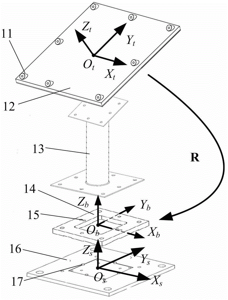
[0079] The relative position of the optical target point is calibrated by NH-SK CNC machine tool to control the precise movement of the auxiliary target point, and the effective stroke of the machine tool is 1000×600×550mm 3 , the freedom of movement in the three directions of the X, Y, and Z axes of the machine tool is on the tool. Fix the target board in the middle of the working table of the machine tool. An infrared LED optical target auxiliary target is fixed at the tool clamping base. The camera is placed about 6m away from the target board.

[0080] The two preset coordinate positions (unit mm) in the machine tool coordinate system are (0.00, 588.00, 485.00) and (955.00, 0.00, 0.00), then the standard length f...


PUM


Abstract

The invention discloses a visual target plate device for calibrating a component mounting attitude and a calibration method, and designs a visual target plate consisting of a visual target surface, an extending rod and a matched fixture. According to the visual target plate, a whole calibration method for a relative position relation of target points in the visual target plate as well as a visual target surface and matched fixture geometric relation is provided. The calibration method comprises the following steps of: calibrating the relative position relation of the optical target points on the target point by a single-camera photographing and measuring method through auxiliary target points which is formed by precision movement and have determined distances; and then controlling the visual target plate to do specific movement by a precisely controlled moving platform, and calibrating relative attitudes of a target surface coordinate system and matched fixture coordinates according to positions of the moving visual target points in the camera by a multi-point perspective algorithm. According to the designed and calibrated visual target plate device provided by the invention, the attitude of a mounting base in a machine body complex mechanism can be measured; and a requirement for flexible automatic site assembling of airplanes can be met.

Description

technical field [0001] The invention belongs to the fields of visual measurement and posture detection, and in particular relates to a visual target board device and a calibration method for component installation posture calibration. Background technique [0002] During the aircraft assembly process, the installation and calibration of airborne components play a vital role in the combat performance of the aircraft. Modern combat aircraft generally have a variety of airborne equipment such as artillery and missiles, as well as a head-up display (HUD), a forward-looking infrared imaging system (FLIR), an attitude reference system (AHRS), and an inertial navigation system (INU). Aircraft guidance and control systems. In order to ensure the effectiveness of the positioning of airborne components, the installation attitude of these components needs to be calibrated. [0003] The traditional calibration method mainly uses tools such as spirit level and theodolite to calibrate t...

Claims


Application Information

Patent Timeline
Patent Type & Authority Applications(China)
IPC IPC(8): G01C11/00
Inventor 叶南杨博文富帅赵秋华张丽艳
Owner SHANXI ZHIDIAN TECH CO LTD
Why Eureka
Try Eureka