A screw thread mold

A technology for removing screw threads and molds, applied in the field of screw removal molds, can solve problems such as cumbersomeness, affecting the quality of tapping threads, setting cooling systems, etc.

Active Publication Date: 2015-08-19
宏利科技(苏州)有限公司
View PDF4 Cites 0 Cited by
  • Summary
  • Abstract
  • Description
  • Claims
  • Application Information

AI Technical Summary

Problems solved by technology

[0002] Some medical liquid output gate products are equipped with slots, and the inner wall of the slot needs to be provided with threads. At this stage, the screws on the inner wall of the product are set by the screw with the outer wall rotating around its own central axis, so as to ensure the stability of the product. Tapping the groove, because a lot of heat will be generated during the tapping process, once the screw is heated, it will expand, which will destroy the size of the thread on the outer wall of the screw, and then affect the precision of the product tapping, so for some short And for products with a larger diameter, such as a product with a diameter of 30mm, a cooling system is installed in the tapping screw to cool the screw so that the accuracy of the tapping will not be affected by the high temperature, but due to the current The way of tapping is that the screw rotates around its own central axis to tap the product. After forming the product, another set of molds is required to separate the screw from the product. The screw used for tapping does not have an ejection mechanism; in addition, For some products with long shape, small diameter and a certain depth of thread, such as products with a diameter of about 15mm, due to its small diameter, it is impossible to install a cooling system in the screw, which will affect the quality of tapping. In addition, Another set of mold is needed to separate the screw from the product, which is cumbersome

Method used


Image

  • A screw thread mold
  • A screw thread mold
  • A screw thread mold

Examples


Embodiment Construction

[0025] The preferred embodiments of the present invention will be described in detail below in conjunction with the accompanying drawings, so that the advantages and features of the present invention can be more easily understood by those skilled in the art, so as to define the protection scope of the present invention more clearly.

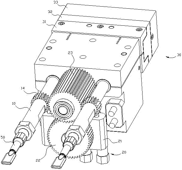
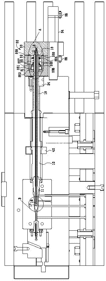
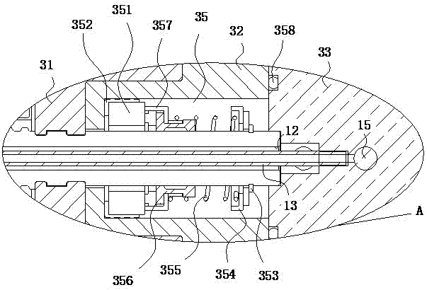
[0026] refer to figure 1 , figure 2 , image 3 , Figure 4 Shown, a kind of unthreading mold, it comprises gear core rod 10, driving unit 20, and one end of gear core rod 10 is provided with tapping thread 11, and tapping thread 11 is used for tapping product 50, gear The end face of the other end of the core rod 10 is provided with a deep hole 12, and a water pipe 13 is arranged in the deep hole 12, and a first predetermined gap is left between the water pipe 13 and the inner wall of the deep hole 12 to form a back cavity 16, which extends into the gear core rod 10 One end of the water pipe 13 and the bottom of the deep hole 12 leave a secon...


PUM


Abstract

The invention discloses a thread demoulding mould which comprises a gear type core rod and a driving unit. A tapped thread is arranged at one end of the gear type core rod, a deep hole is formed in an end face of the other end of the gear type core rod, and a water pipe is positioned in the deep hole. The driving unit comprises a hydraulic servo motor, a first driving gear and a second driving gear, wherein the first driving gear is connected with the hydraulic servo motor, and the first driving gear and the second driving gear are meshed. A core rod gear is arranged on the outer wall of the gear type core rod, and the second driving gear is meshed with the core rod gear. The thread demoulding mould further comprises a stroke traction sleeve which can rotate around a self central shaft, wherein the stroke traction sleeve is sleeved on the gear type core rod with a transmission thread. The thread demoulding mould can cool products of different specifications in a tapping process and removes additional moulds to demould the products.

Description

technical field [0001] The invention relates to a mould, in particular to a thread stripping mould. Background technique [0002] Some medical liquid output gate products are equipped with slots, and the inner wall of the slot needs to be provided with threads. At this stage, the screws on the inner wall of the product are set by the screw with the outer wall rotating around its own central axis, so as to ensure the stability of the product. Tapping the groove, because a lot of heat will be generated during the tapping process, once the screw is heated, it will expand, which will destroy the size of the thread on the outer wall of the screw, and then affect the precision of the product tapping, so for some short And for products with a larger diameter, such as a product with a diameter of 30mm, a cooling system is installed in the tapping screw to cool the screw so that the accuracy of the tapping will not be affected by the high temperature, but due to the current The way ...

Claims


Application Information

Patent Timeline
Patent Type & Authority Patents(China)
IPC IPC(8): B23G1/16B23G1/44
Inventor 王锋平
Owner 宏利科技(苏州)有限公司
Why Eureka
Try Eureka