All-wheel drive motor vehicle

a technology of all-wheel drive and motor vehicles, which is applied in the direction of electric vehicles, electric devices, electric energy vehicles, etc., can solve the problems of more compact auxiliary systems (cooling, generators, etc., and achieves the effects of less power, affecting the size and cost, and being less powerful

Inactive Publication Date: 2006-11-02
KRAUSS MAFFEI WEGMANN GMBH & CO KG
View PDF12 Cites 6 Cited by
  • Summary
  • Abstract
  • Description
  • Claims
  • Application Information

AI Technical Summary

Benefits of technology

[0008] In the embodiment of the motor vehicle according to the invention, the advantages of a mechanical power train are combined with the advantages of an electrical or hydraulic single wheel drive. In general, the drive unit is comprised of single wheel drives, which, on every axle, can be coupled together via transverse locking means and which can be connected via universal joint shafts and longitudinal locking means so as to form a combined power train following the pattern of a locked mechanical power train. This system provides an electrical or hydraulic power train, which, although configured in a compact manner, allows the vehicle to surmount even extreme obstacles (slope / step). The motors can be designed less powerful, which affects the size and cost and also leads to more compact auxiliary systems (cooling, generator, power electronics).
[0009] Furthermore, the system enables a central parking brake or arresting means, which leads to advantages regarding space and weight. Unsprung masses are hence reduced and the emission of heat from the service brake is improved, due to a better oncoming flow against the brake disk and / or the service brake saddle.

Problems solved by technology

The motors can be designed less powerful, which affects the size and cost and also leads to more compact auxiliary systems (cooling, generator, power electronics).

Method used


Image

  • All-wheel drive motor vehicle
  • All-wheel drive motor vehicle
  • All-wheel drive motor vehicle

Examples


Embodiment Construction

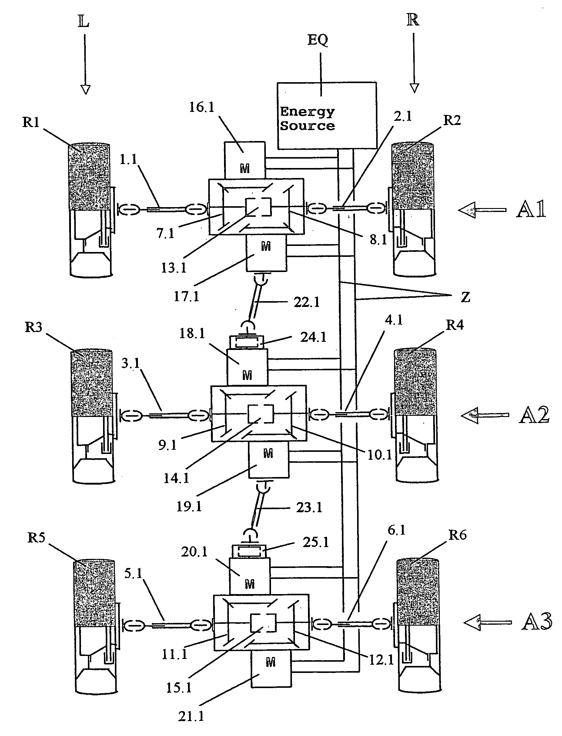
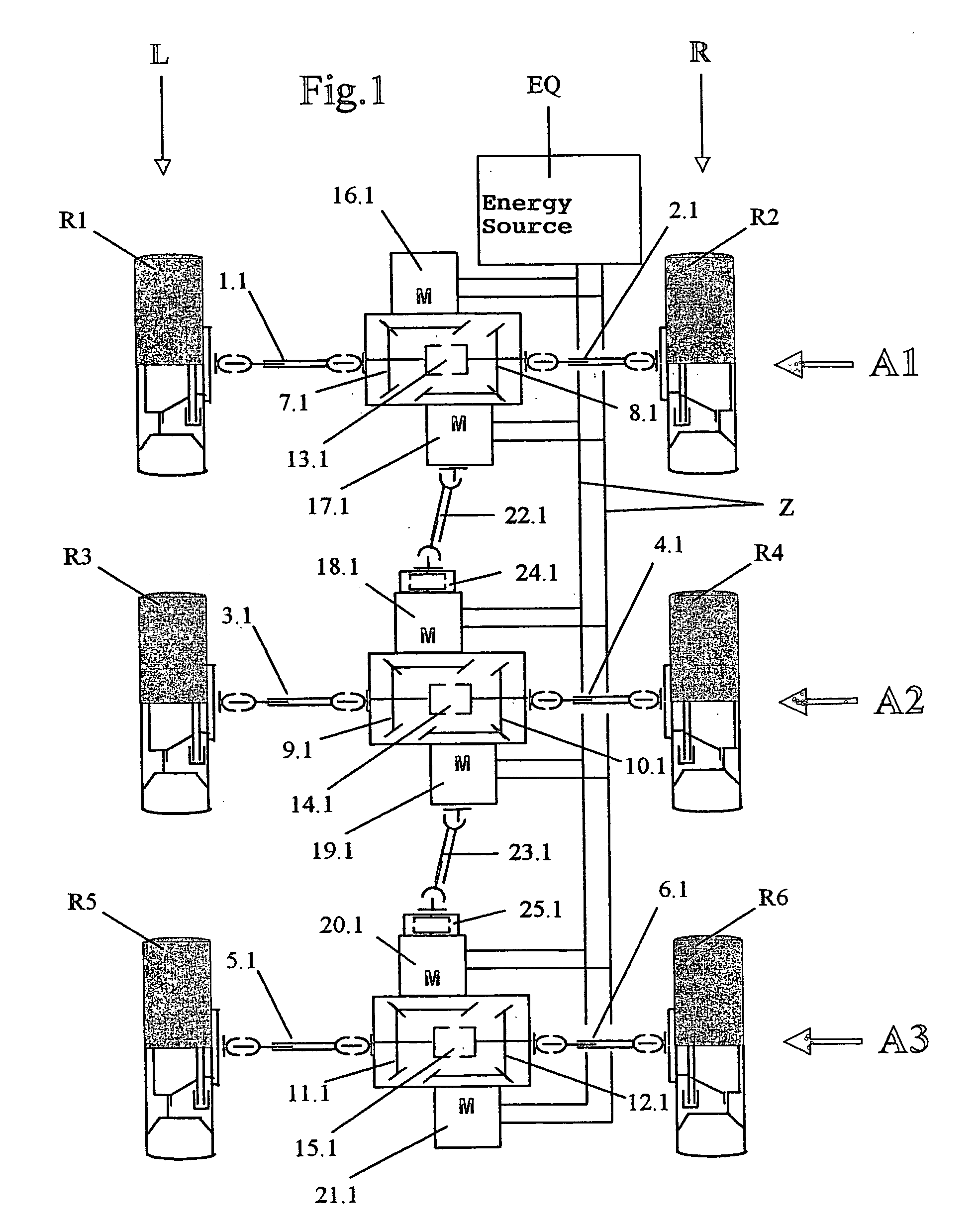
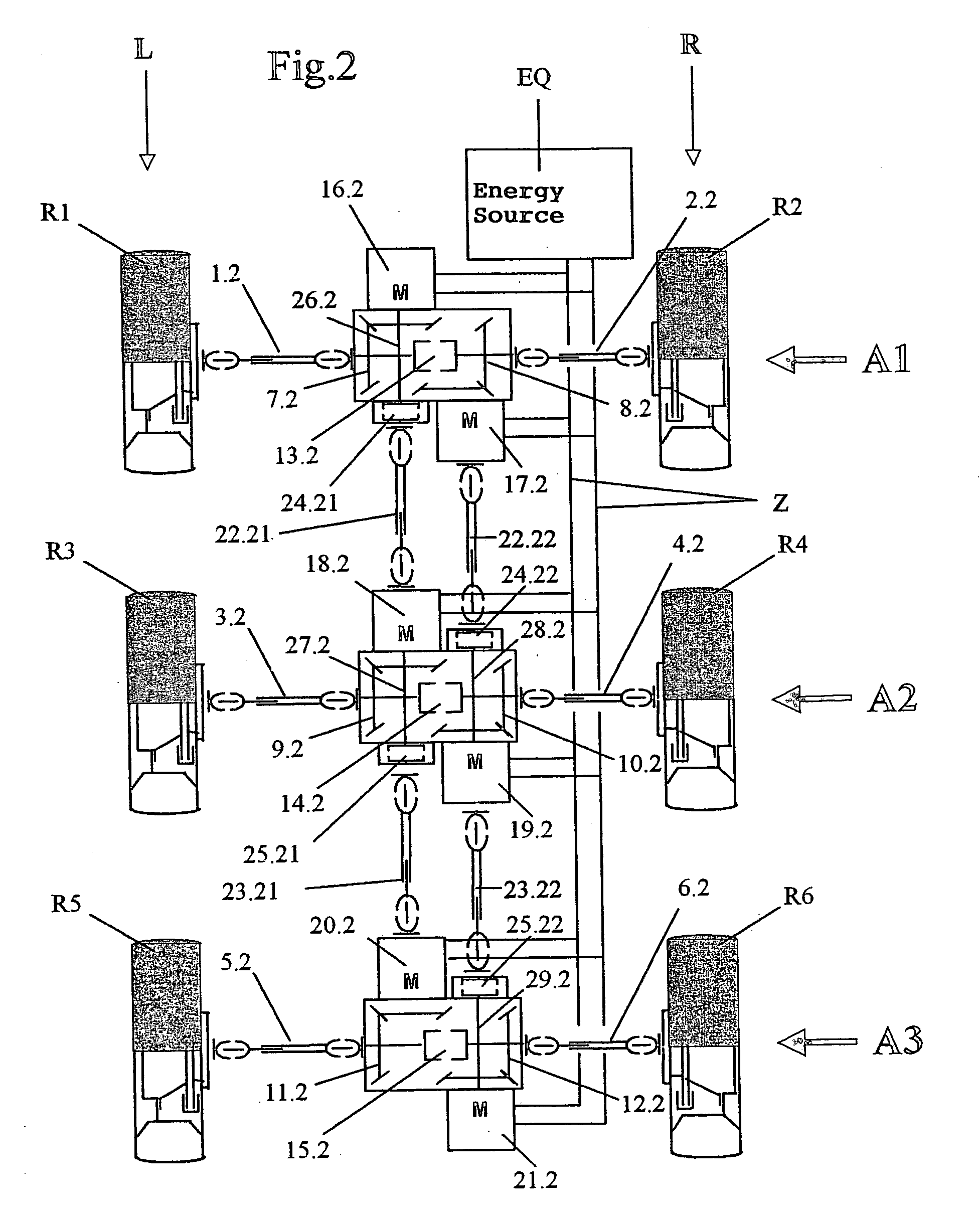
[0020] In all of the drawings, the left side of the vehicle is labeled with L and the right side of the vehicle is labeled with R. Each drawing illustrates a power train comprising three axles, thus having a first axle A1, a second axle A2 and a third axle A3. The wheels R1 and R2 are associated with the first axle A1, the wheels R3 and R4 are associated with the second axle A2, and the wheels R5 and R6 are associated with the third axle A3.

[0021] All vehicles have an electrical or hydraulic source of energy EQ, which can be realized in different and known manners and is not described in further detail. The energy supply for the motors M of the drive unit is realized my means of the supply lines Z.

[0022] In the first embodiment of the power train represented in FIG. 1, the wheels R1 and R2 of the axle A1 are each connected to an associated transmission or gear unit 7.1 or 8.1, respectively, by means of the universal joint shafts 1.1 and 2.1 that extend transverse to the longitudin...


PUM


Abstract

An all-wheel drive motor vehicle having at least two wheel axles and comprising an electrical or hydraulic drive unit having a plurality of electric or hydraulic motors connected to an electrical or hydraulic energy source. Each motor is associated with a drive wheel and drives such wheel via a transmission. The motors that are associated with a given one of the wheel axles are adapted to be coupled with one another via a shiftable transverse locking device. At least one of the motors on a first side of the vehicle is adapted to be coupled, via a shiftable longitudinal locking device, with one of the motors associated with a different one of the wheel axles on the same side or on a second side of the vehicle.

Description

BACKGROUND OF THE INVENTION [0001] The present invention relates to an all-wheel drive motor vehicle having at least two wheel axles and an electrical or hydraulic drive unit with a plurality of electric or hydraulic motors connected to an electrical or hydraulic energy source, each motor being associated with one of the drive wheels and driving such wheel via a transmission. [0002] Motor vehicles of that kind are known. A motor vehicle of the aforementioned configuration that is configured as a hybrid vehicle with a diesel-electric drive unit is e.g. described, for example, in DE 101 21 372 A1. [0003] Furthermore, motor vehicles that have a mechanical power train and moreover vehicles in which e.g. the front axle is driven mechanically whereas the rear axle is provided with an additional electric motor are generally known. [0004] Motor vehicles with a mechanical power train have the disadvantage that turning the vehicle about its vertical axis is impossible [when the vehicle is sta...

Claims


Application Information

Patent Timeline
Patent Type & Authority Applications(United States)
IPC IPC(8): B60K17/356B60K6/46B60K6/52
CPCB60K6/46B60K6/52B60K7/0007B60K7/0015B60K17/043Y02T10/6265B60K17/356B60K2007/0061B60L2220/46Y02T10/6217B60K17/22Y02T10/62
Inventor GRABMAIER, NORBERTHELF, KURT
Owner KRAUSS MAFFEI WEGMANN GMBH & CO KG
Why Eureka
Try Eureka