a switch cabinet

A switchgear and isolation switch technology, applied in electrical switches, substations/switch layout details, electrical components, etc., can solve the problems of low reliability of action, hidden dangers, complicated operation, etc., to prevent false closing of vacuum circuit breakers, mutual The effect of perfect lock function and simple overall structure

Active Publication Date: 2015-09-23
厦门闽光电气实业有限公司
View PDF5 Cites 0 Cited by
  • Summary
  • Abstract
  • Description
  • Claims
  • Application Information

AI Technical Summary

Problems solved by technology

[0002] Switchgear is a commonly used power distribution equipment in power systems. Switchgear usually includes cabinets, circuit breakers, isolating switches and other mechanisms. Safety is one of the most important technical indicators of switchgear. In order to prevent misuse during the use of switchgear To open and close the circuit breaker, prevent the on-load opening and closing of the isolating switch, and prevent accidental entry into the live interval and other safety hazards, a mechanical interlock mechanism or an electrical interlock mechanism must be installed in the switch cabinet. The interlocking function between the various actions of the device, isolating switch, and cabinet door usually requires multiple sets of interlocking mechanisms. The structure is relatively complicated and the operation is cumbersome; Low, there will be some security risks

Method used


Image

  • a switch cabinet
  • a switch cabinet
  • a switch cabinet

Examples


Embodiment Construction

[0034] The present invention will be described in further detail below in conjunction with the accompanying drawings and specific embodiments.

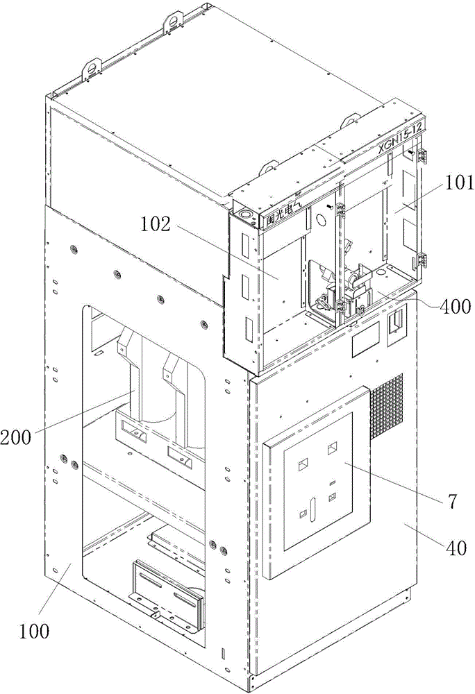
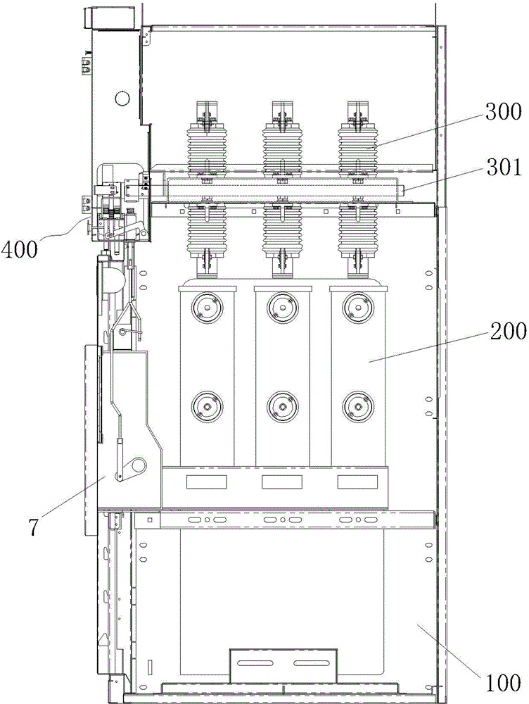
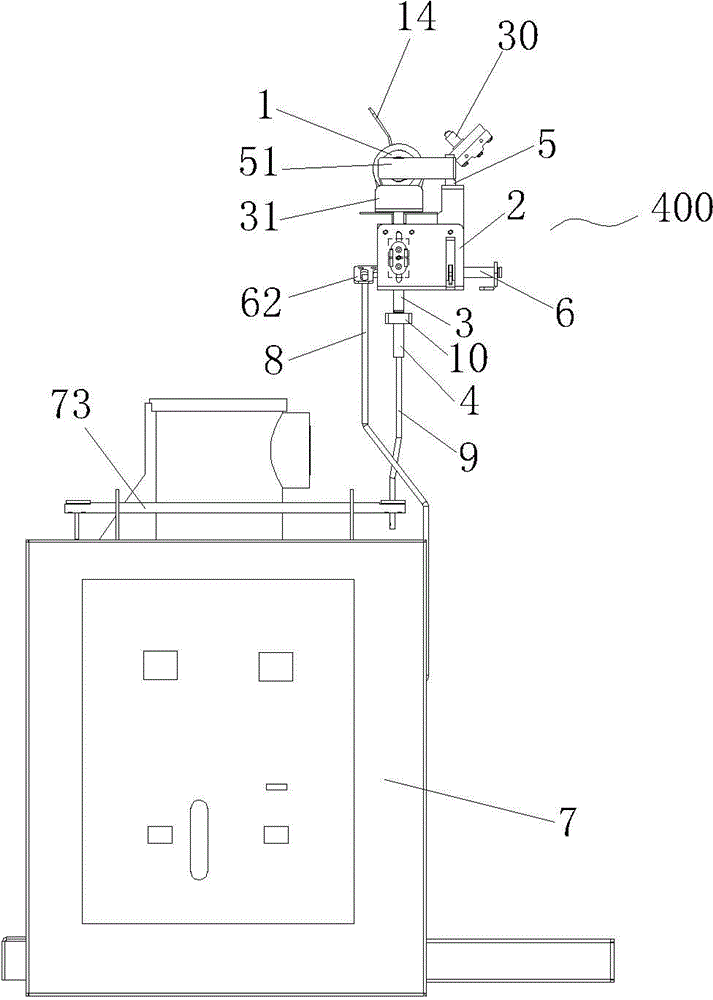
[0035] Figure 1 to Figure 11 As shown, a switch cabinet includes a cabinet body 100, an operating room 101 and an instrument room 102 are arranged on the front upper part of the cabinet body 100, a cabinet door 40 is installed on the front middle and lower part of the cabinet body 100, and a vacuum is installed in the middle part of the cabinet body 100. For circuit breaker 200, isolating switch 300 is installed in the upper part of cabinet body 100. The lower incoming line column of isolating switch 300 is electrically connected with the upper outgoing line column of vacuum circuit breaker 200. The upper part of the cabinet body 100 is provided with a relief hole for the operating mechanism 7 of the vacuum circuit breaker 200 to facilitate the operation of the operating mechanism 7 of the vacuum circuit breaker 200. The side of the ...


PUM


Abstract

The invention discloses a switch cabinet which comprises a cabinet body. A cabinet door is installed on the cabinet body. A vacuum circuit breaker is installed in the middle inside the cabinet body. A disconnecting switch is installed on the upper portion inside the cabinet body. A mutual interlocking mechanism is installed on the cabinet body. The mutual interlocking mechanism comprises a shaft sleeve. The rear end of the shaft sleeve is connected with an operational shaft of the disconnecting switch. A first cam and a second cam are fixed on the peripheral face of the shaft sleeve. A support is arranged below the shaft sleeve. A first ejector rod, a second ejector rod and a pull rod are installed on the support. A rotating shaft is arranged behind the support. A switch-on shaft and a releasing shaft are arranged on an operational mechanism of the vacuum circuit breaker. The pull rod is connected with the switch-on shaft through the rotating shaft and a first connecting rod. The second ejector rod is connected with the releasing shaft through a second connecting rod. The lower end of the first ejector rod is matched with the cabinet door. An upper cover plate is fixed at the upper end of the pull rod. A lower cover plate is fixed on the upper portion of the first ejector rod. The upper cover plate and the lower cover plate are located in front of the shaft sleeve. The switch cabinet is simple and compact in structure, complete in mutual interlocking function, high in safety performance and easy and convenient to operate.

Description

technical field [0001] The invention relates to the technical field of switchgear manufacturing. Background technique [0002] Switchgear is a commonly used power distribution equipment in power systems. Switchgear usually includes cabinets, circuit breakers, isolating switches and other mechanisms. Safety is one of the most important technical indicators of switchgear. In order to prevent misuse during the use of switchgear To open and close the circuit breaker, prevent the on-load opening and closing of the isolating switch, and prevent accidental entry into the live interval and other safety hazards, a mechanical interlock mechanism or an electrical interlock mechanism must be installed in the switch cabinet. The interlocking function between the various actions of the device, isolating switch, and cabinet door usually requires multiple sets of interlocking mechanisms. The structure is relatively complicated and the operation is cumbersome; Low, there will be some securi...

Claims


Application Information

Patent Timeline
Patent Type & Authority Patents(China)
IPC IPC(8): H02B1/00H01H9/26H01H9/20
Inventor 苏水郑房帅王清鑫
Owner 厦门闽光电气实业有限公司
Why Eureka
Try Eureka