

Guide changing exhausting channel
A technology of exhaust ducts and changing guide plates, applied in vertical pipes, building components, buildings, etc., can solve the problems of poor smoke exhaust, large system resistance, easy to be put on construction waste, etc., to ensure smoke exhaust performance, The effect of reducing internal static pressure and facilitating flue gas emission
- Summary
- Abstract
- Description
- Claims
- Application Information
AI Technical Summary
Problems solved by technology
Method used
Image

Examples
Embodiment 1
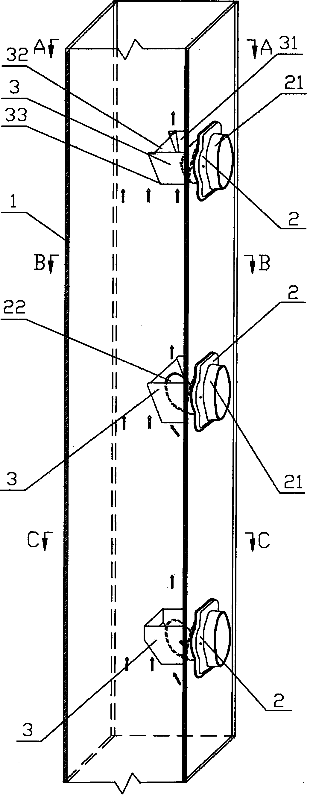
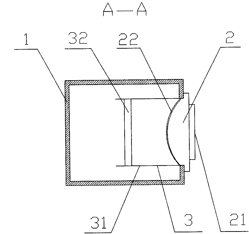
[0033] Variable guide exhaust structure, such as figure 1 , 2 , shown in 5, comprise exhaust channel 1 and fire check valve 2, described exhaust channel 1 is provided with bottomless guide tube 3, and the air outlet of fire check valve 2 is arranged in bottomless guide tube 3.
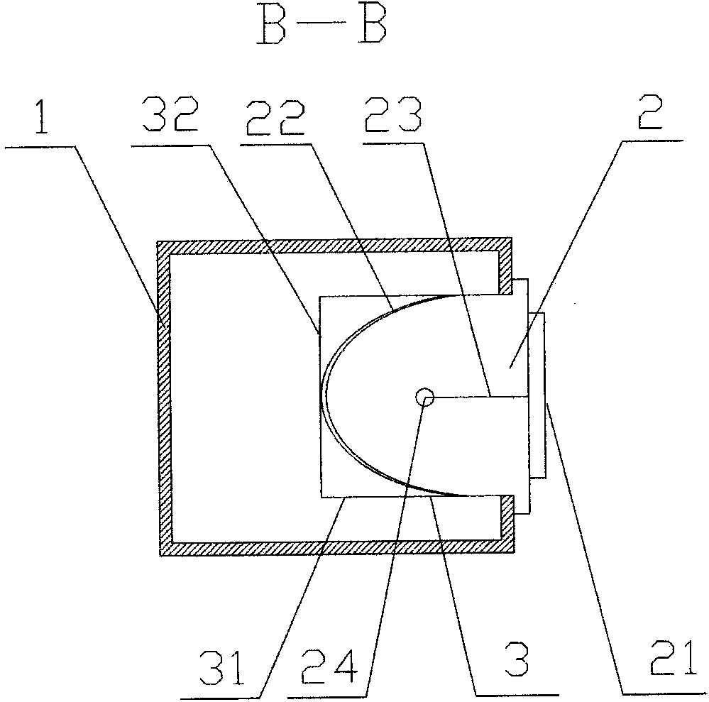
[0034] The bottomless guide pipe 3 is fixedly connected with the fire check valve 2. The fire check valve 2 includes an air inlet 21 , and a valve plate 22 is arranged inside the fire check valve 2 . The fire check valve 2 is provided with a valve plate 22, and the valve plate 22 is connected with the valve body of the fire check valve 2 through the rebound device 4. The rebound device 4 is a tension spring 23, and the bottom end of the valve plate 22 is hinged with the valve body of the fire check valve 2. The valve plate 22 is provided with a connecting buckle 24, which is connected by the tension spring 23 between the connecting buckle 24 and the valve body.
[0035] The bottom end of the valve p...
Embodiment 2
[0040] Variable guide exhaust structure, such as figure 1 , 3 , 6, 8, and 9, including the exhaust duct 1 and the fire check valve 2, the exhaust duct 1 is provided with a bottomless guide pipe 3, and the air outlet of the fire check valve 2 is set on the bottomless guide Inside tube 3.
[0041] The bottomless guide pipe 3 is fixedly connected with the fire check valve 2. The fire check valve 2 includes an air inlet 21 , and a valve plate 22 is arranged inside the fire check valve 2 . When the valve plate 22 is opened, the lower opening of the bottomless guide pipe 3 is blocked. The fire check valve 2 is provided with a valve plate 22, and the valve plate 22 is connected with the valve body of the fire check valve 2 through the rebound device 4. The rebound device 4 includes a connecting rod 42 connected with the connecting buckle 24 provided on the valve plate 22, the connecting rod 42 is connected with the angle spring 43 on the valve body of the fire check valve 2, and ...
Embodiment 3
[0045] Variable guide exhaust structure, such as figure 1 , 4 As shown in .
[0046] The bottomless guide pipe 3 is fixedly connected with the fire check valve 2.
[0047] The fire check valve 2 includes an air inlet 21 , and a valve plate 22 is arranged inside the fire check valve 2 . When the valve plate 22 is opened, the lower opening of the bottomless guide pipe 3 is blocked.
[0048] The bottom end of the valve plate 22 is hinged with the valve body of the fire check valve 2, and the valve plate 22 is provided with a connecting buckle 24, which is connected by a tension spring 23 between the connecting buckle 24 and the valve body. The valve plate 22 is an arc plate. The connecting buckle 24 is arranged in the middle of the valve plate 22 .
[0049] The bottomless guide pipe 3 includes two symmetrically arranged side plates 31, and a variable guide plate 32 arranged between the two side plates 31. The two side plates 31, the variable guide plate 32 and the inner wall...
PUM
 Abstract
Description
Claims
Application Information