Air returning device on material discharging side of drying channel

A technology of discharge side and drying tunnel, applied in drying, dryer, drying gas arrangement and other directions, can solve the problems of heat loss in drying tunnel, waste of energy, temperature deviation of drying tunnel, etc., and achieve the effect of saving heat

Inactive Publication Date: 2013-10-16
王兆进
View PDF4 Cites 0 Cited by
  • Summary
  • Abstract
  • Description
  • Claims
  • Application Information

AI Technical Summary

Problems solved by technology

[0002] At present, there is no return air device on the discharge side of the drying tunnel, so when the material needs to be taken out, the discharge port needs to be opened, resulting in a large amount of heat loss in the drying tunnel, which not only leads to heat loss in the drying tunnel, wastes energy, but also causes temperature deviation

Method used


Image

  • Air returning device on material discharging side of drying channel

Examples


Embodiment Construction

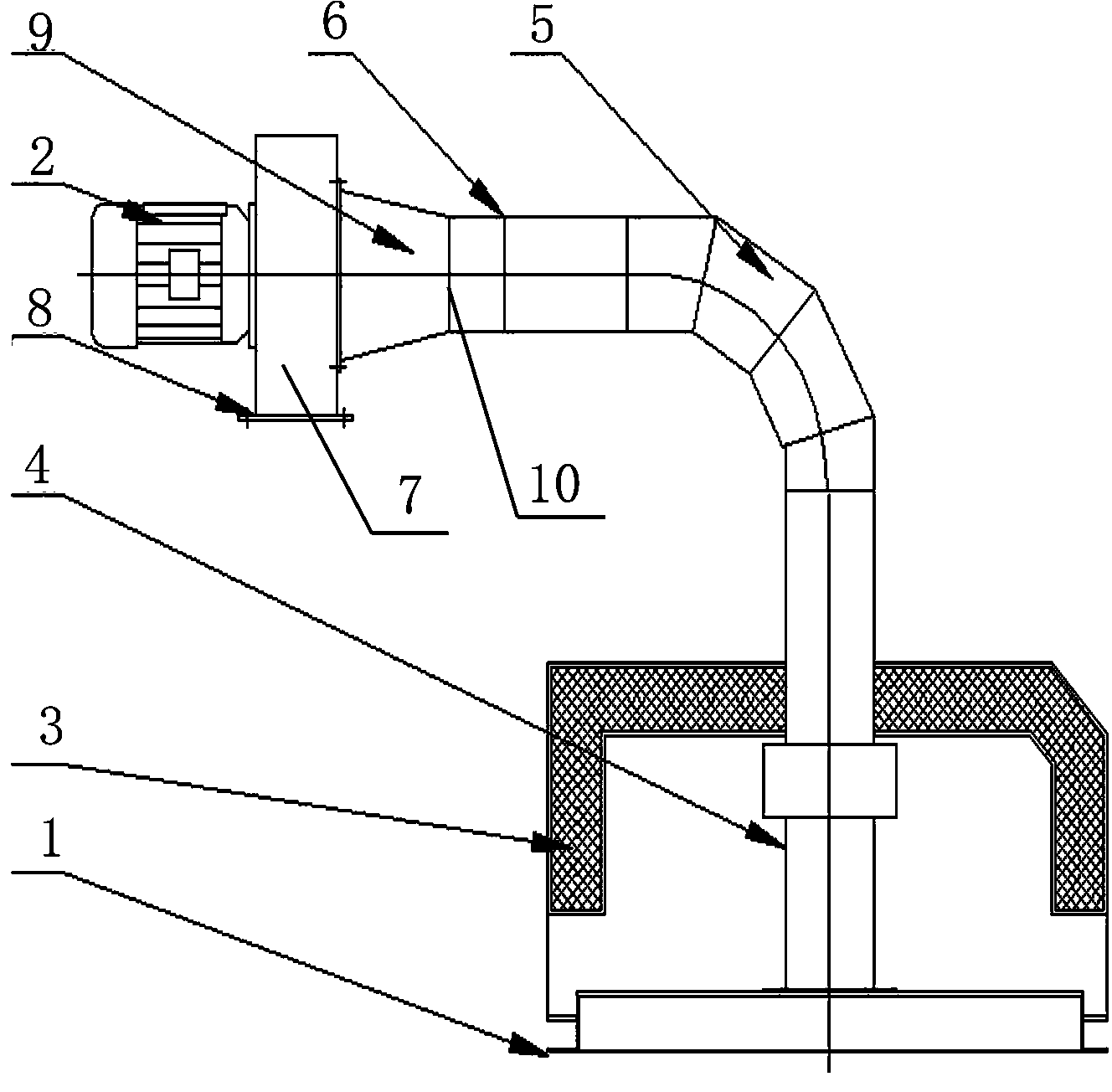
[0008] exist figure 1 Among them, the present invention provides a return air device on the discharge side of the drying tunnel, which is provided with a return air box 1 and a return air fan 2, and a return air cover 3 is provided on the top of the return air box 1, and a return air return box is provided in the return air box 1 The air duct 4 and the return air duct 4 pass upward through the return air cover 3 and extend out of the return air box 1, and then are connected with an elbow 5 and a straight pipe 6 in turn. One end of the straight pipe 6 is connected to the elbow 5, and the other end of the straight pipe 6 It communicates with the tuyere 7 of the return air fan 2, and a damper adjustment plate 8 is provided at the lower part of the tuyere 7, and a tapered pipe 9 is provided between the other end of the straight pipe 6 and the tuyere 7 of the return air fan 2 for transition connection , the other end of the straight pipe 6 is connected with the tapered pipe 9 throu...


PUM


Abstract

The invention discloses an air returning device on a material discharging side of a drying channel. The air returning device on the material discharging side of the drying channel is provided with an air returning box (1) and an air returning draught fan (2). An air returning hood (3) is arranged on the top of the air returning box (1), an air returning pipe (4) is arranged in the air returning box (1), the air returning pipe (4) penetrates upwards through the air returning hood (3), stretches out of the air returning box (1) and then is connected with a bending pipe (5) and a straight pipe (6) in sequence, one end of the straight pipe (6) is connected with the bending pipe (5), the other end of the straight pipe (6) is communicated with an air mouth (7) of the air returning draught fan (2), and a ventilation door regulating plate (8) is arranged on the lower portion of the air port (7).

Description

technical field [0001] The invention relates to a return air device at the discharge side of a drying tunnel. Background technique [0002] At present, there is no return air device on the discharge side of the drying tunnel, so when the material needs to be taken out, the discharge port needs to be opened, resulting in a large amount of heat loss in the drying tunnel, which not only leads to heat loss in the drying tunnel, wastes energy, but also causes temperature deviation. Contents of the invention [0003] The invention provides a return air hood on the discharge side of a drying tunnel, which can not only prevent heat loss in the drying tunnel, but also ensure the temperature in the drying tunnel. [0004] The present invention adopts the following technical solutions: a return air device on the discharge side of the drying tunnel, which is provided with a return air box and a return air fan, a return air cover is arranged on the top of the return air box, and a ret...

Claims


Application Information

Patent Timeline
Patent Type & Authority Applications(China)
IPC IPC(8): F26B21/00
Inventor 王兆进
Owner 王兆进
Why Eureka
Try Eureka