Unlock instant, AI-driven research and patent intelligence for your innovation.

Robot

A robot and drive mechanism technology, applied in the field of robots, can solve problems such as damage to the inner thread of the shell, crushed thread teeth, and the inability of the robot to achieve the effect of a large movable range

Active Publication Date: 2013-10-23
SEIKO EPSON CORP
View PDF9 Cites 4 Cited by
  • Summary
  • Abstract
  • Description
  • Claims
  • Application Information

AI Technical Summary

Problems solved by technology

However, if the robot described in Patent Document 1 is repeatedly maintained, the internal thread of the casing will be damaged, that is, the thread teeth will be crushed.
In this case, maintenance cannot be performed with the cover removed
In addition, since the cover is in a state of being removed, as a result, the drive mechanism is exposed, the frequency of maintenance increases, and safety cannot be ensured, resulting in the robot being unusable

Method used


Image

  • Robot
  • Robot
  • Robot

Examples


Embodiment Construction

[0061] Hereinafter, the robot of the present invention will be described in detail based on preferred embodiments shown in the drawings.

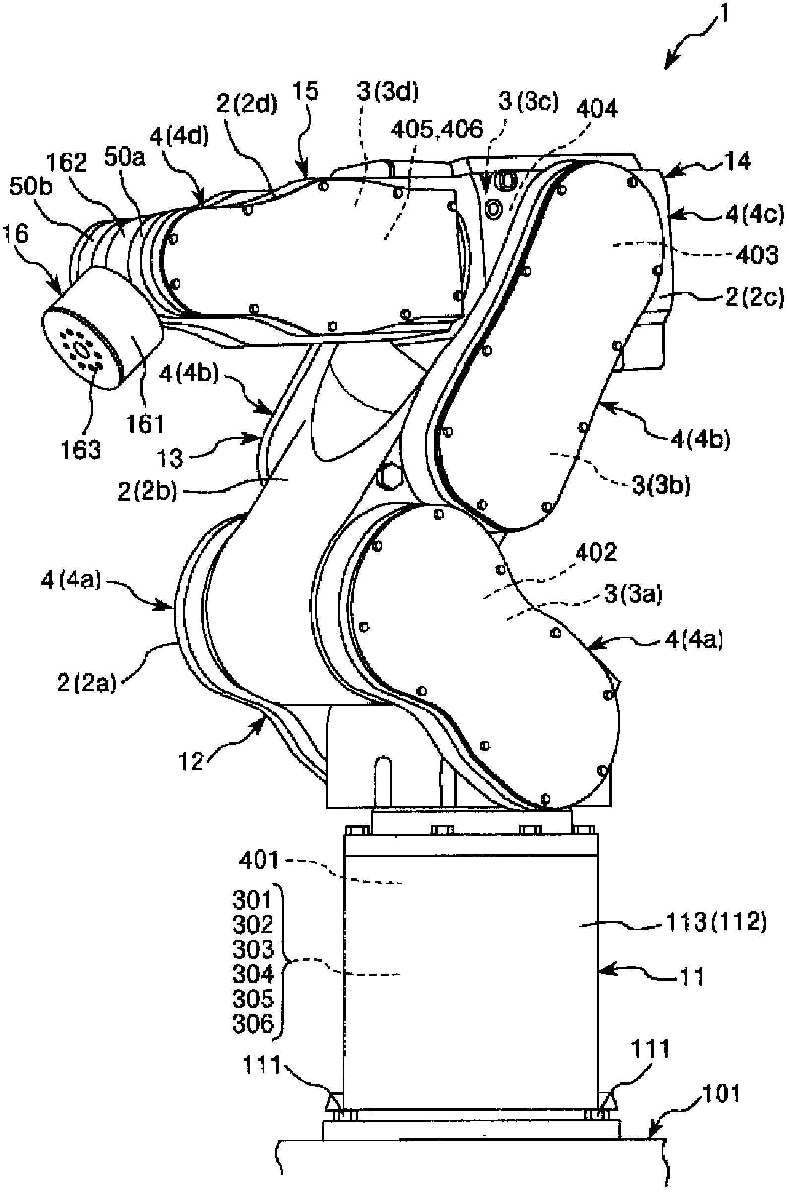
[0062] figure 1 It is a perspective view of the robot of the present invention viewed from the front side, figure 2 It is a perspective view of the robot of the present invention viewed from the back side, image 3 is a simplified diagram of the robot of the present invention, Figure 4 is a block diagram of the main parts of the robot of the present invention, Figure 5 It is a perspective view showing the use state (installation state) of the robot of the present invention, Figure 6 is an exploded perspective view of a representative one of the plurality of arms included in the robot of the present invention, Figure 7 yes Figure 6 The A-A line sectional view in the Figure 8 yes Figure 6 The B-B line sectional view in, Figure 9 It is an enlarged cross-sectional view of a frame included in the robot of the present invention, ...


PUM


Abstract

A robot includes an arm. The arm includes a long-shaped arm body having a storing section configured of a concave section which is formed to open to a side surface thereof; a driving mechanism which is stored in the storing section and has a motor; and a sealing section airtightly sealing the storing section. The sealing section includes a frame body which has a frame shape along an edge of the opening section opened to the side surface of the storing section and is adhered to the edge with adhesive, and has a plurality of female screws in which a plurality of bolts are screwed, respectively; a cover which is detachably installed on the frame body by the bolts which are screwed in the female screws and covers the storing section in a installed state; and a packing interposed between the frame body and the cover.

Description

technical field [0001] The present invention relates to robots. Background technique [0002] Conventionally, there is known a robot including a base and a plurality of arms supported so as to be displaceable with respect to the base and connected to each other (for example, refer to Patent Document 1). In the robot described in Patent Document 1, for example, one arm has: a casing as the arm main body; a motor, pulley, belt, etc. housed in the casing as a driving mechanism; and a cover covering the driving mechanism. A plurality of internal threads are formed on the housing. Then, the cover is fixed to the housing by screwing the bolts into the respective internal threads, that is, by the bolts. [0003] In addition, a gasket and a plate supporting the gasket are interposed between the casing and the cover, and these members are collectively fixed together with the cover by bolts. In this way, in the robot described in Patent Document 1, a so-called "joint fastening" met...

Claims


Application Information

Patent Timeline
Patent Type & Authority Applications(China)
IPC IPC(8): B25J19/00
CPCB25J9/0009B25J19/0075B25J18/00Y10S901/23Y10T74/20317Y10T74/20305
Inventor 母仓政次大轮拓矢
Owner SEIKO EPSON CORP