Electro-optic display and materials for use therein

a technology applied in the field of optical display and materials, can solve the problems of inadequate service life of optical display, unable to meet the needs of the user, and gas-based electrophoretic media are susceptible to the same types of problems, so as to achieve the effect of increasing the viscosity of the matrix and preventing widespread us

Inactive Publication Date: 2009-05-19
E INK CORPORATION
View PDF283 Cites 678 Cited by
  • Summary
  • Abstract
  • Description
  • Claims
  • Application Information

AI Technical Summary

Benefits of technology

[0058]This invention also provides a process for forming a layer of an anisotropic adhesive having greater conductivity perpendicular to the plane of the layer than in this plane, the process comprising: dispersing a plurality of conductive particles in an adhesive matrix, the particles having a complex conductivity differing from that of the matrix; applying to the particles / matrix mixture an electric or magnetic field effective to cause the particles to form conductive strands extending substantially perpendicular to the plane of the layer; and increasing the viscosity of the matrix to prevent the particles moving out of the strands.

Problems solved by technology

Nevertheless, problems with the long-term image quality of these displays have prevented their widespread usage.
For example, particles that make up electrophoretic displays tend to settle, resulting in inadequate service-life for these displays.
Such gas-based electrophoretic media appear to be susceptible to the same types of problems due to particle settling as liquid-based electrophoretic media, when the media are used in an orientation which permits such settling, for example in a sign where the medium is disposed in a vertical plane.
Indeed, particle settling appears to be a more serious problem in gas-based electrophoretic media than in liquid-based ones, since the lower viscosity of gaseous suspending fluids as compared with liquid ones allows more rapid settling of the electrophoretic particles.
However, vacuum lamination of the two parts of an electro-optic display in this manner imposes stringent requirements upon the lamination adhesive used, especially in the case of a display using an encapsulated electrophoretic medium.
The lamination adhesive must have adequate flow properties at the lamination temperature to ensure high quality lamination, and in this regard, the demands of laminating encapsulated electrophoretic and some other types of electro-optic media are unusually difficult; the lamination has to be conducted at a temperature of not more than about 110° C. since the medium cannot be exposed to substantially higher temperatures without damage, but the flow of the adhesive must cope with the relatively uneven surface of the capsule-containing layer, the surface of which is rendered irregular by the underlying capsules.
The lamination temperature should indeed be kept as low as possible, and room temperature lamination would be ideal, but no commercial adhesive has been found which permits such room temperature lamination.
As discussed in detail in the aforementioned U.S. Pat. No. 6,831,769, a lamination adhesive used in an electro-optic display must meet certain electrical criteria, and this introduces considerable problems in the selection of the lamination adhesive.
However, in such applications, the electrical properties of the lamination adhesive are not relevant, and consequently the commercial manufacturers pay no heed to such electrical properties.
If the resistivity of the adhesive layer is too high, a substantial voltage drop will occur within the adhesive layer, requiring an increase in voltage across the electrodes.
Increasing the voltage across the electrodes in this manner is undesirable, since it increases the power consumption of the display, and may require the use of more complex and expensive control circuitry to handle the increased voltage involved.
On the other hand, if the adhesive layer, which extends continuously across the display, is in contact with a matrix of electrodes, as in an active matrix display, the volume resistivity of the adhesive layer should not be too low, or lateral conduction of electric current through the continuous adhesive layer may cause undesirable cross-talk between adjacent electrodes.
Also, since the volume resistivity of most materials decreases rapidly with increasing temperature, if the volume resistivity of the adhesive layer is too low, the performance of the display at temperatures substantially above room temperature is adversely affected.
While it may be apparent that there should be a relationship between the volume resistivities of the electro-optic medium and the lamination adhesive used in an electro-optic display, it has been discovered, as noted in the aforementioned U.S. Pat. No. 6,831,769, that other problems which have been observed in the operation of electro-optic displays are attributable to the electrical and related properties of the lamination adhesive.
However, although these materials perform well when the displays are first produced, after the resultant displays have been operated for substantial periods of time (of the order of hundreds of hours) at room temperature, or stored for a similar period, the performance of the display suffers substantial degradation.
This degradation increases at lower temperatures (10° C. or below) and with time, so that after long periods the switching of the whole display is affected at room temperature.
This degradation in optical performance with time is an important factor in limiting the service life of the displays.
Obviously, self-erasing is highly undesirable in that it reverses (or otherwise distorts, in the case of a grayscale display) the desired optical state of the display.
However, as the conductivity of the lamination adhesive is increased at constant pixel resolution and storage capacitance, charge supplied to a pixel is leaked to neighboring pixels; this decreases the voltage gradient across the electro-optic material and counteracts the effect of increasing the lamination adhesive conductivity.
In addition, as already mentioned this lateral charge leakage may cause a change in the optical state of neighboring pixels.
However, the lamination adhesive is not necessarily the only polymeric component present between the electrodes in an electro-optic display.

Method used


Image

  • Electro-optic display and materials for use therein
  • Electro-optic display and materials for use therein
  • Electro-optic display and materials for use therein

Examples


example 1

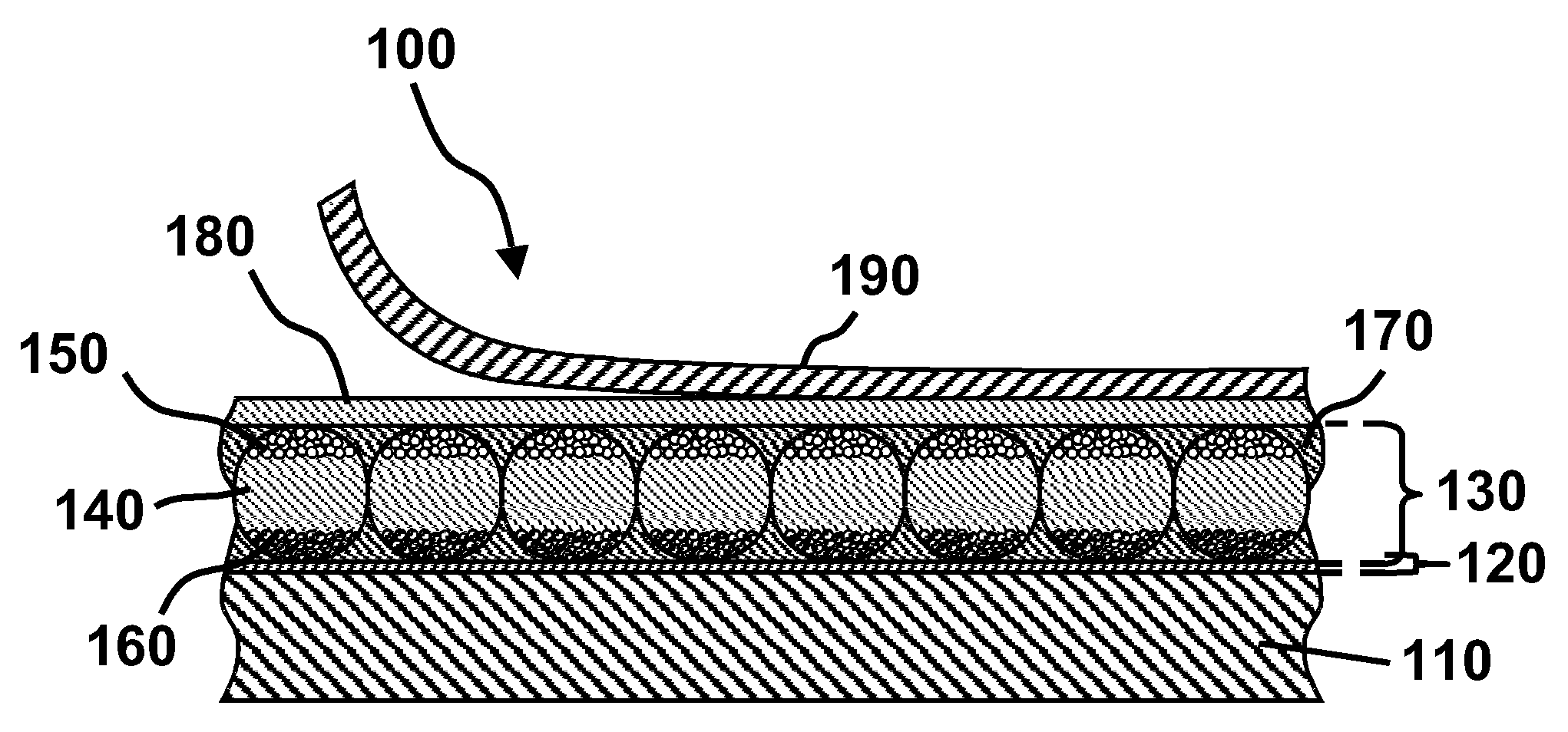
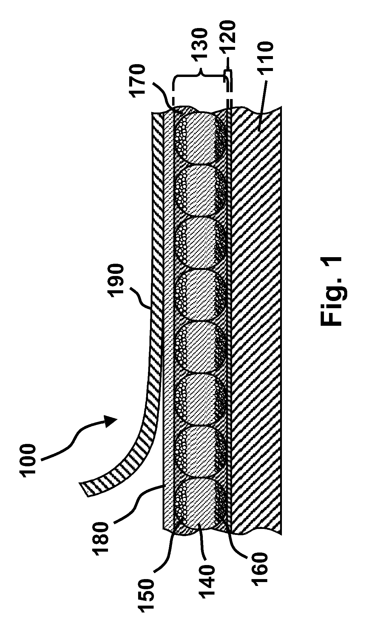
[0242]This Example describes the preparation of a display of the present invention using a gelatin / acacia microencapsulated electrophoretic medium.

[0243]A Preparation of Oil (Internal) Phase

[0244]To a 1 L flask is added 0.5 g of Oil Blue N (Aldrich, Milwaukee, Wis.), 0.5 g of Sudan Red 7B (Aldrich), 417.25 g of Halogenated hydrocarbon Oil 0.8 (Halogenated Hydrocarbon Products Corp., River Edge, N.J.), and 73.67 g of Isopar-G (Exxon, Houston, Tex.—“ISOPAR” is a Registered Trade Mark). The mixture is stirred at 60° C. for six hours and is then cooled to room temperature. 50.13 g of the resulting solution is placed in a 50 mL polypropylene centrifuge tube, to which is added 1.8 g of titanium dioxide (TiO2) (E. I. du Pont de Nemours & Company, Wilmington, Del.), 0.78 g of a 10% solution of OLOA 1200 (Chevron, Somerset, N.J.), in Halogenated hydrocarbon Oil 0.8, and 0.15 g of Span 85 (Aldrich). This mixture is then sonicated for five minutes at power 9 in an Aquasonic Model 75 D sonicato...

example 2

[0283]This Example illustrates the improved stability of the volume resistivity of the aforementioned R 9320 upon prolonged storage provided by blending the material with the aforementioned U KA 8713.

[0284]Test samples, using pure R 9320 and U KA 8713, and 90 / 10, 75 / 25 and 50 / 50 w / w per cent blends of these two materials, were prepared in the following manner. The blend, adjusted to 40 % solids content, was coated, using a doctor blade set at 150 μm, on to a 5 mil (127 μm) sheet of ITO-coated polyester masked on one edge, so that the masked area could later serve as an electrode. The resultant coating was dried in an oven at 50° C., for 20 minutes to produce a dry film approximately 60 μm thick. The resultant adhesive-coated film was then laminated, by vacuum or roll lamination, to a second sheet of ITO-coated polyester so that the adhesive was in contact with both ITO layers. The samples thus prepared were stored at ambient temperature and humidity for 2500 hours. The electrical pr...

example 3

[0286]This Example illustrates the improved stability of the volume resistivity and dielectric constant of the aforementioned R 9320 upon prolonged storage provided by blending the material with the aforementioned R 9000.

[0287]Example 2 was repeated, except that R 9000 was substituted for U KA 8713, that the storage period was 4000 hours, and that the volume resistivity measurements were supplemented by measurements of the dielectric constant of the blends using the same impedance spectrometer as previously mentioned. The volume resistivity results are shown in FIG. 6 of the accompanying drawings and the dielectric constant results in FIG. 7.

[0288]From FIG. 6, it will be seen that, although the volume resistivities of both R 9320 and R 9000 underwent substantial changes over the test period, the blends had much more stable resistivities. In particular, the performance of the 50 / 50 w / w blend was outstanding, displaying a variation by less than a factor of 2 throughout the storage per...


PUM

PropertyMeasurementUnit
enthalpyaaaaaaaaaa
dielectric constantaaaaaaaaaa
volume resistivityaaaaaaaaaa

Abstract

An electro-optic display comprises a layer (130) of a solid electro-optic material, at least one electrode disposed adjacent the layer (130) of electro-optic material, and a layer (180) of a lamination adhesive interposed between the layer (130) of electro-optic material and the electrode, the lamination adhesive (180) having a higher electrical conductivity in a direction perpendicular to the layer of lamination adhesive than in the plane of the layer.

Description

REFERENCE TO RELATED APPLICATIONS[0001]This application is a continuation-in-part of application Ser. No. 10 / 708,121, filed Feb. 10, 2004 (Publication No. 2004 / 0252360, now U.S. Pat. No. 7,110,163), which itself is a continuation-in-part of application Ser. No. 10 / 064,389, filed Jul. 9, 2002 (Publication No. 2003 / 0025855, now U.S. Pat. No. 6,831,769), which in turn claims benefit of application Ser. No. 60 / 304,117, filed Jul. 9, 2001. The aforementioned application Ser. No. 10 / 708,121 claims benefit of application Ser. No. 60 / 319,934, filed Feb. 11, 2003 and application Ser. No. 60 / 319,973, filed Feb. 26, 2003.[0002]This application is also a continuation-in-part of copending application Ser. No. 10 / 605,024, filed Sep. 2, 2003 (Publication No. 2004 / 0155857), which claims benefit of application Ser. No. 60 / 319,516, filed Sep. 3, 2002.[0003]This application is also a continuation-in-part of application Ser. No. 10 / 907,065, filed Mar. 18, 2005 (Publication No. 2005 / 0146774, now U.S. Pa...

Claims


Application Information

Patent Timeline
Patent Type & Authority Patents(United States)
IPC IPC(8): G02B26/00G03G13/00G09G3/34C09J7/10
CPCC08K3/22C09J7/00C09J7/0207C09J9/02C09J11/04G02B26/026G02F1/167G02F1/172C08K3/0066C09J2205/102G02F1/133305G02F2001/133368G02F2202/16G02F2202/28H05K3/323C08K3/017C09J7/38C09J7/10G02F1/16757C09J2301/408G02F1/133368
Inventor AMUNDSON, KARL R.ZEHNER, ROBERT W.WEBBER, RICHARD M.GERAMITA, KATHERINEZHANG, LIBINGLOXLEY, ANDREW L.DUTHALER, GREGG M.RITTER, JOHN E.STEINER, MICHAEL L.HOLMAN, MAVYN M.ABRAMSON, JUSTIN J.CROSSLEY, GLEN
Owner E INK CORPORATION
Why Eureka
Try Eureka