Product for coating wellbore screens

a wellbore and screen technology, applied in the direction of coatings, wellbore/well accessories, sealing/packing, etc., can solve the problems of not designing any of these coating materials, it is difficult to successfully circulate cleaning treatments, etc., to prevent flow capacity damage, minimize flow capacity damage, and high viscosity

Inactive Publication Date: 2008-04-22
CONSTIEN VERNON GEORGE
View PDF33 Cites 152 Cited by
  • Summary
  • Abstract
  • Description
  • Claims
  • Application Information

AI Technical Summary

Benefits of technology

[0020]The present invention is a product and process for coating wellbore screens and liners. The coating of the present invention serves to prevent flow capacity damage to sand control screens or slotted liners as the screens or liners are placed into the wellbore and then melts or dissolves and releases materials which react with potential screen plugging materials and thus minimizes flow capacity damage to the screen or liner. The coating of the present invention is composed of a binding agent and one or more reactive materials or components, such as enzymes, chelants, organic acids, surface active agents, oxidizers and other materials which are capable of dissolving, degrading, or dispersing potentially plugging materials, such as for example materials commonly found in drilling fluids, filtercakes formed from these drilling fluids, hydraulic fracturing fluids, high viscosity completion fluid “pills”, and gravel packing fluids.

Problems solved by technology

However, often the screen will become plugged with bridging agents, polymers, and drill solids that are left in the wellbore at the completion of the drilling operation.
This is particularly a problem in high angle or horizontal wellbores where it is very difficult to successfully circulate cleaning treatments such as acids or enzymes around the screen to remove remaining drilling fluid filtercake prior to beginning production.
Until now, none of these coating materials have been designed to also include materials which can be released after the screen or slotted liner is in place and react with or solubilize plugging materials that may be in the wellbore.

Method used


Image

  • Product for coating wellbore screens
  • Product for coating wellbore screens
  • Product for coating wellbore screens

Examples


Embodiment Construction

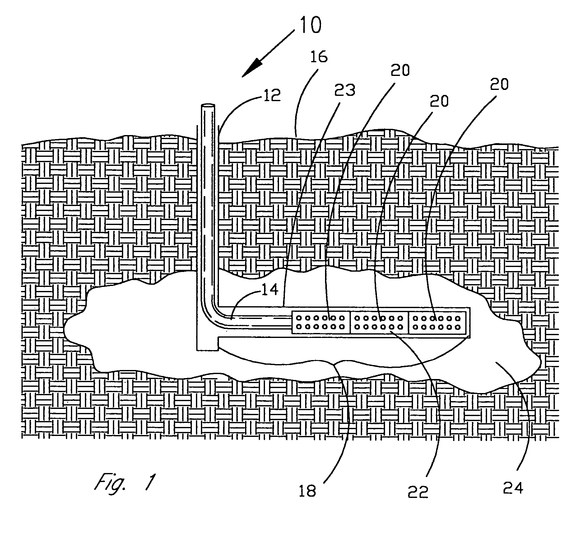
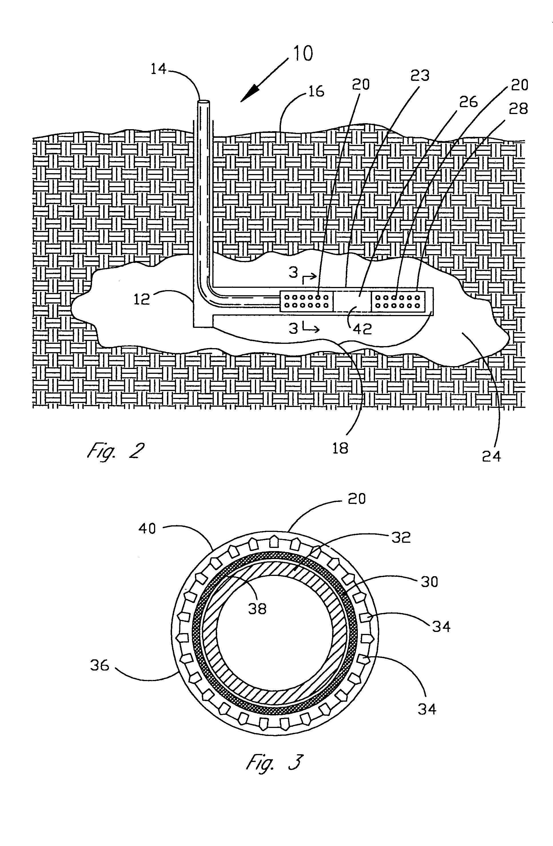
[0033]Referring now to FIG. 1, there is illustrated an oil or gas well 10 with a horizontal portion 18. The well 10 is shown with a well casing 12 and production tubing 14 that is located inside the casing 12 and extends from the ground surface 16 downward into the well 10. As illustrated in FIG. 1, the horizontal portion 18 of the completed well 10 contains a plurality of screen segments 20 that are connected together to form a continuous screen 22 that may extend horizontally for over one thousand feet in a wellbore 23 created in the formation 24.

[0034]The present invention is a product and process for coating these types of wellbore screens 20. Although the invention is shown in the illustrations in association with screens 20 for a horizontally completed well 10, the invention is not so limited and may be used in association with any type of well. Also, the invention is described hereafter for use in association with screens 20, but the invention is not so limited and may be use...


PUM

PropertyMeasurementUnit
melting pointaaaaaaaaaa

Abstract

Coatings for well screens that protect the screens from damage as they are inserted into the wellbore and once in the well, release reactive materials to react with and degrade potentially plugging materials such as drill solids, fluid filtercakes, fluid loss additives, and drilling fluids. The coatings can be specifically designed for individual well conditions and are comprised of a binder that either melts or dissolves within the wellbore and one or more reactive materials such as acids, enzymes, surfactants, chelants, oxidizers or free radical generators and the like which are released into the screen and the near wellbore area and which are effective in degrading or dissolving materials which could potentially plug the screen.

Description

CROSS-REFERENCE TO RELATED APPLICATIONS[0001]This is a continuation in part application of U.S. patent application Ser. No. 10 / 062,096 entitled “Product for Coating Wellbore Screens” filed on Jan. 31, 2002 now U.S. Pat. No. 6,831,044 which was a divisional application of U.S. patent application Ser. No. 09 / 627,145 entitled “Product and Process for Coating Wellbore Screens” that was filed on Jul. 27, 2000 now U.S. Pat. No. 6,392,185.BACKGROUND OF THE INVENTION[0002]1. Field of the Invention[0003]The present invention relates to compositions for preventing flow capacity damage to wellbore screens and slotted liners. More specifically, the present invention relates to a coating that is applied to wellbore screens or slotted liners prior to insertion of the screens or slotted liners into the wellbore. The coating is comprised of reactive materials mixed with a binder. The coating protects the screens and slotted liners during insertion into the wellbore.[0004]Also, after the screens and...

Claims


Application Information

Patent Timeline
Patent Type & Authority Patents(United States)
IPC IPC(8): E21B43/08C09D5/00C09K8/00C09K8/52C09K8/536
CPCC09K8/52C09K8/536E21B43/08Y10S507/902
Inventor CONSTIEN, VERNON GEORGE
Owner CONSTIEN VERNON GEORGE
Why Eureka
Try Eureka