Electro-optic display and lamination adhesive for use therein

a technology applied in the field of optical display and adhesive composition, can solve the problems of preventing widespread use, imposing stringent requirements on lamination adhesive, inadequate service life of optical display, etc., and achieves the reduction of the handling of devices, the effect of increasing the lamination strength and reducing the size of the thermal oven

Inactive Publication Date: 2004-12-16
E INK CORPORATION
View PDF99 Cites 153 Cited by
  • Summary
  • Abstract
  • Description
  • Claims
  • Application Information

AI Technical Summary

Benefits of technology

0107] Several advantages are inherent in the use of radiation cured systems, particularly water-reducible systems. Reduced handling of devices before and after lamination can be realized from the ability of the water-reducible systems to cure without having the water removed, but some water removal prior to curing has been found to gives increased lamination strength. Curing can be achieved through transparent polyethylene terephthalate, or, as in the system of FIG. 4, curing may be allowed to proceed after irradiation; either case allows for a very uniform lamination with a central adhesive layer that transforms from liquid to solid. The need for large thermal ovens is reduced when using ultra-violet curing systems, with resultant sig

Problems solved by technology

Nevertheless, problems with the long-term image quality of these displays have prevented their widespread usage.
For example, particles that make up electrophoretic displays tend to settle, resulting in inadequate service-life for these displays.
However, vacuum lamination of the two parts of an electro-optic display in this manner imposes stringent requirements upon the lamination adhesive used, especially in the case of a display using an encapsulated electrophoretic medium.
The lamination adhesive must have adequate flow properties at the lamination temperature to ensure high quality lamination, and in this regard, the demands of laminating encapsulated electrophoretic and some other types of electro-optic media are unusually difficult; the lamination has be conducted at a temperature of not more than about 110.degree. C. since the medium cannot be exposed to substantially higher temperatures without damage, but the flow of the adhesive must cope with the relatively uneven surface of the capsule-containing layer, the surface of which is rendered irregular by the underlying capsules.
The lamination temperature should indeed be kept as low as possible, and room temperature lamination would be ideal, but no commercial adhesive has been found which permits such room temperature lamination.
As discussed in detail in the aforementioned copending application Ser. No. 10/064,389, a lamination adhesive used in an electro-optic display must meet certain electrical criteria, and this

Method used


Image

  • Electro-optic display and lamination adhesive for use therein
  • Electro-optic display and lamination adhesive for use therein
  • Electro-optic display and lamination adhesive for use therein

Examples


Embodiment Construction

[0110] This Example describes the preparation of a display of the present invention using a gelatin / acacia microencapsulated electrophoretic medium.

[0111] A Preparation of Oil (Internal) Phase

[0112] To a 1L flask is added 0.5 g of Oil Blue N (Aldrich, Milwaukee, Wis.), 0.5 g of Sudan Red 7B (Aldrich), 417.25 g of Halogenated hydrocarbon Oil 0.8 (Halogenated Hydrocarbon Products Corp., River Edge, N.J.), and 73.67 g of lsopar-G (Exxon, Houston, Tex.--"ISOPAR" is a Registered Trade Mark). The mixture is stirred at 60.degree. C. for six hours and is then cooled to room temperature. 50.13 g of the resulting solution is placed in a 50 mL polypropylene centrifuge tube, to which is added 1.8 g of titanium dioxide (TiO.sub.2) (E. I. du Pont de Nemours & Company, Wilmington, Del.), 0.78 g of a 10% solution of OLOA 1200 (Chevron, Somerset, N.J.), in Halogenated hydrocarbon Oil 0.8, and 0.15 g of Span 85 (Aldrich). This mixture is then sonicated for five minutes at power 9 in an Aquasonic Mode...


PUM


Abstract

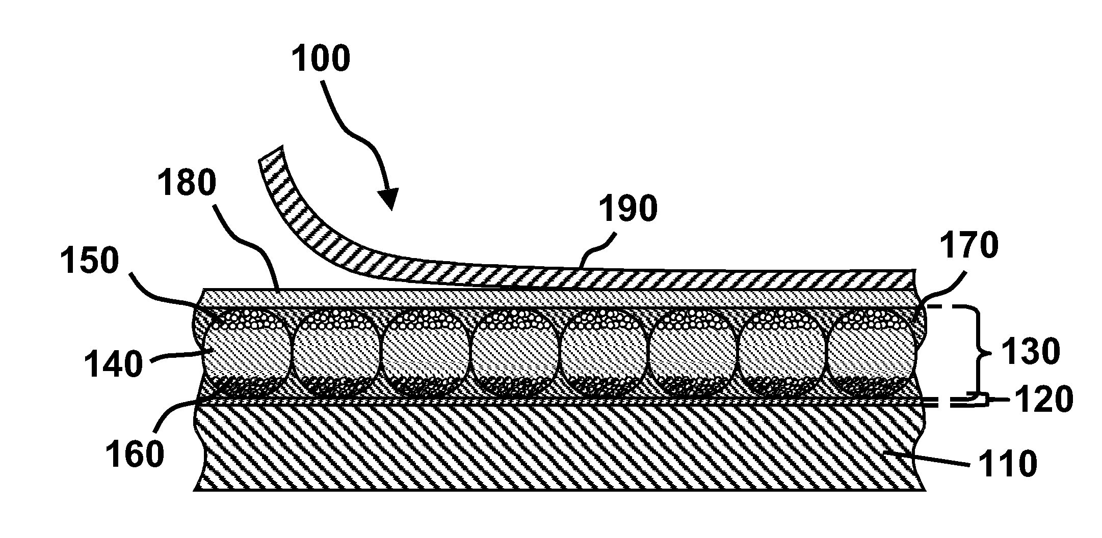
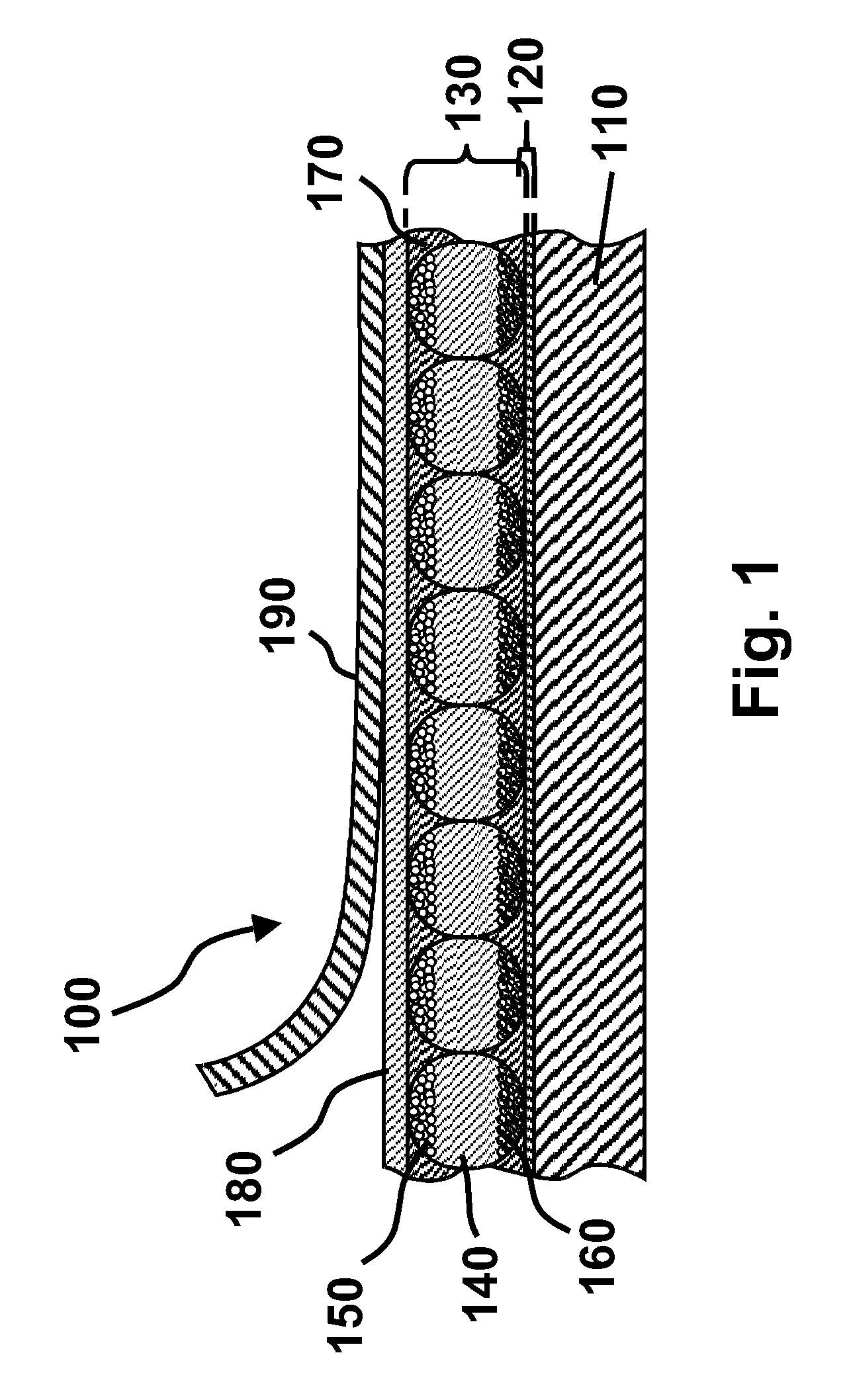
An electro-optic display comprises a layer (130) of a solid electro-optic material, at least one electrode disposed adjacent the layer (130) of electro-optic material, and a layer (180) of a lamination adhesive interposed between the layer (130) of electro-optic material and the electrode, the lamination adhesive (180) having a higher electrical conductivity in a direction perpendicular to the layer of lamination adhesive than in the plane of the layer.

Description

[0001] This application is a continuation-in-part of copending application Ser. No. 10 / 064,389 (Publication No. 2003 / 0025855), filed July 9, 2002, which claims benefit of application Ser. No. 60 / 304,117, filed July 9, 2001. This application also claims benefit of application Ser. No. 60 / 319,934, filed Feb. 11, 2003 and application Ser. No. 60 / 319,973, filed Feb. 26, 2003.[0002] This application is also related to the following applications and patents: (a) application Ser. No. 10 / 329,023 (Publication No. 2003 / 0112491), filed Dec. 24, 2002; (b) application Ser. No. 09 / 140,846, filed Aug. 27, 1998, of which the aforementioned application Ser. No. 10 / 329,023 is a continuation; (c) application Ser. No. 08 / 504,896, filed Jul. 20, 1995 (now U.S. Pat. No. 6,124,851), of which the aforementioned application Ser. No. 09 / 140,846 is a continuation-in-part; (d) application Ser. No. 08 / 983,404, filed Mar. 26, 1999, of which the aforementioned application Ser. No. 09 / 140,846 is a continuation-in-...

Claims


Application Information

Patent Timeline
IPC IPC(8): G02F1/1333G02F1/167G02F1/1675
CPCG02F1/133305G02F1/167G02F2001/133368G02F1/1675G02F1/133368
Inventor WEBBER, RICHARD M.JACOBSON, JOSEPH M.DUTHALER, GREGG M.AMUNDSON, KARL R.ALBERT, JONATHAN D.LOXLEY, ANDREW L.HOLMAN, MAVYN M.CROSSLEY, GLENNGERAMITA, KATHARINE
Owner E INK CORPORATION
Why Eureka
Try Eureka