

System and method for optimizing handover in mobile communication system
- Summary
- Abstract
- Description
- Claims
- Application Information
AI Technical Summary
Benefits of technology
Problems solved by technology
Method used
Image

Examples
Embodiment Construction
[0034] Hereinafter, a preferred embodiment according to the present invention will be described with reference to the accompanying drawings. In the following description of the present invention, a detailed description of known functions and configurations incorporated herein will be omitted when it may make the subject matter of the present invention unclear.
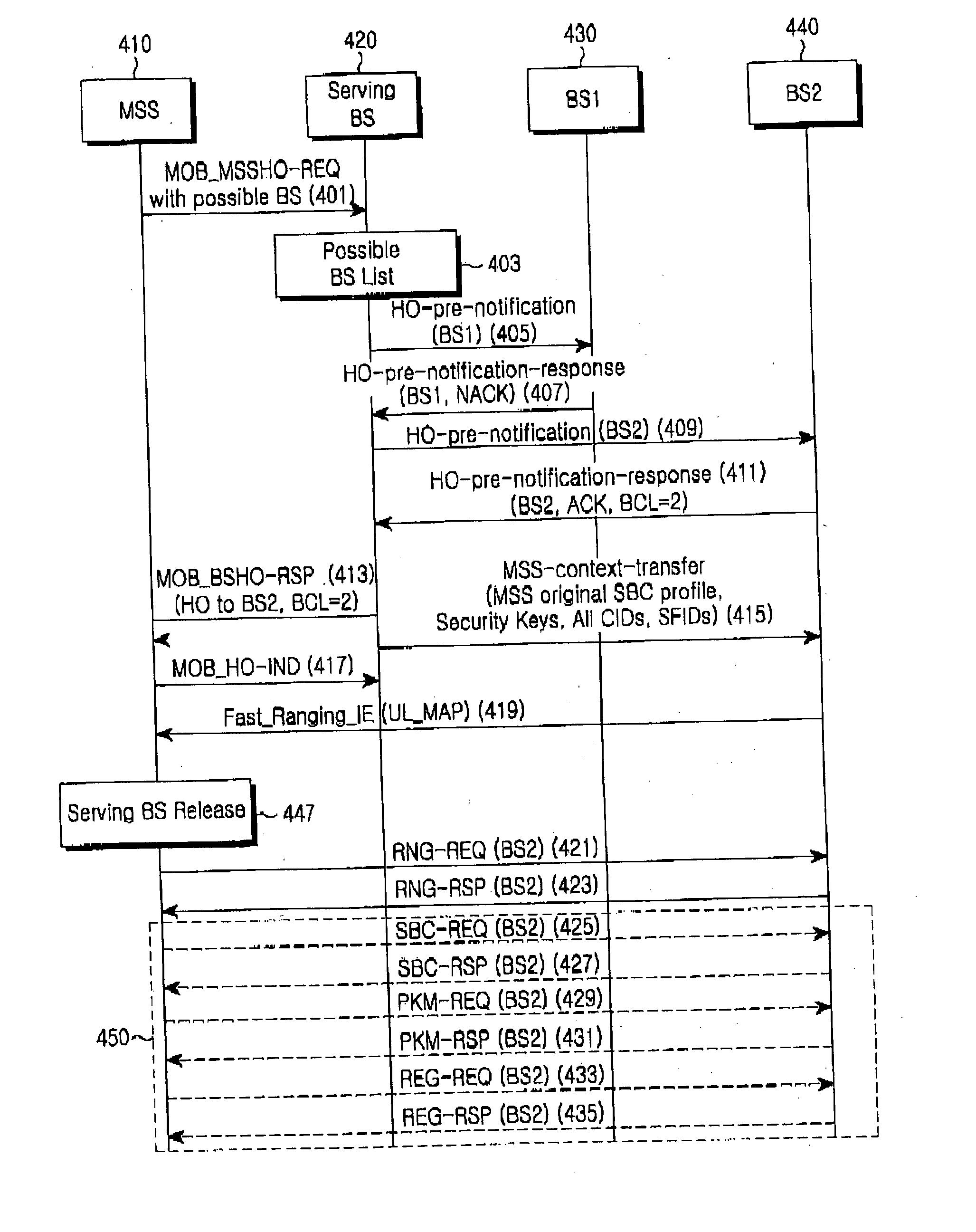
[0035] The present invention proposes a solution for improving a handover process in a Mobile Broadband Wireless Access (MBWA) system. That is, the present invention proposes a solution for optimizing a handover process in order to improve handover performance in a MBWA system. For such optimization, the present invention proposes a stepped backbone communication and polling mechanism and defines a signaling process and message for realizing them.
[0036] The backbone communication according to the present invention includes three levels, that is, a first-level (Level 1) backbone communication, a second-level (Level 2) backbone...
PUM
 Abstract
Description
Claims
Application Information