Method and laboratory system for handling sample tubes and an image analyzing unit

Active Publication Date: 2010-01-28
ROCHE DIAGNOSTICS OPERATIONS INC
View PDF13 Cites 75 Cited by
  • Summary
  • Abstract
  • Description
  • Claims
  • Application Information

AI Technical Summary

Benefits of technology

[0009]Further, it may be provided that a sample tube which is found to be non-system conform is allocated a non-conformity designation. Sample tubes identified/designated as non-system conform are entered into error processing. There are errors which can be cured by the system, as e.g. a no-cap designation. There are also errors which cannot be cured by the system, as, e.g., a tube not in compliance with the required geometrical parameters. In the latter type of errors, error processing may cause the system to transfer the corresponding rack with the non-system conform sample tube to an error position, e.g., for further manual handling, for returning the sample tube to its origin, for disposal etc. According to the invention, a sample tube which is id

Problems solved by technology

Very often, such racks contain tubes with different sizes, heights, diameters, contents, expiration dates of the samples etc., which complicates automated handling so that in some cases further automated insertion of the racks in the test process in the laboratory is not possible, the racks having to be discharged manually.
This facilitates the automated handling of sample tubes as there is no typing according to known types of sample tubes as such a comparison proves to be error-prone.
As a result, system robustness is enhanced because the handling of non-compliant or non-conform tubes with a gripper coul

Method used


Image

  • Method and laboratory system for handling sample tubes and an image analyzing unit
  • Method and laboratory system for handling sample tubes and an image analyzing unit
  • Method and laboratory system for handling sample tubes and an image analyzing unit

Examples


Embodiment Construction

[0025]Reference will now be made in detail to some embodiments, examples of which are illustrated in the accompanying drawings. Wherever possible, the same reference numbers are used throughout the drawings to refer to the same or like parts.

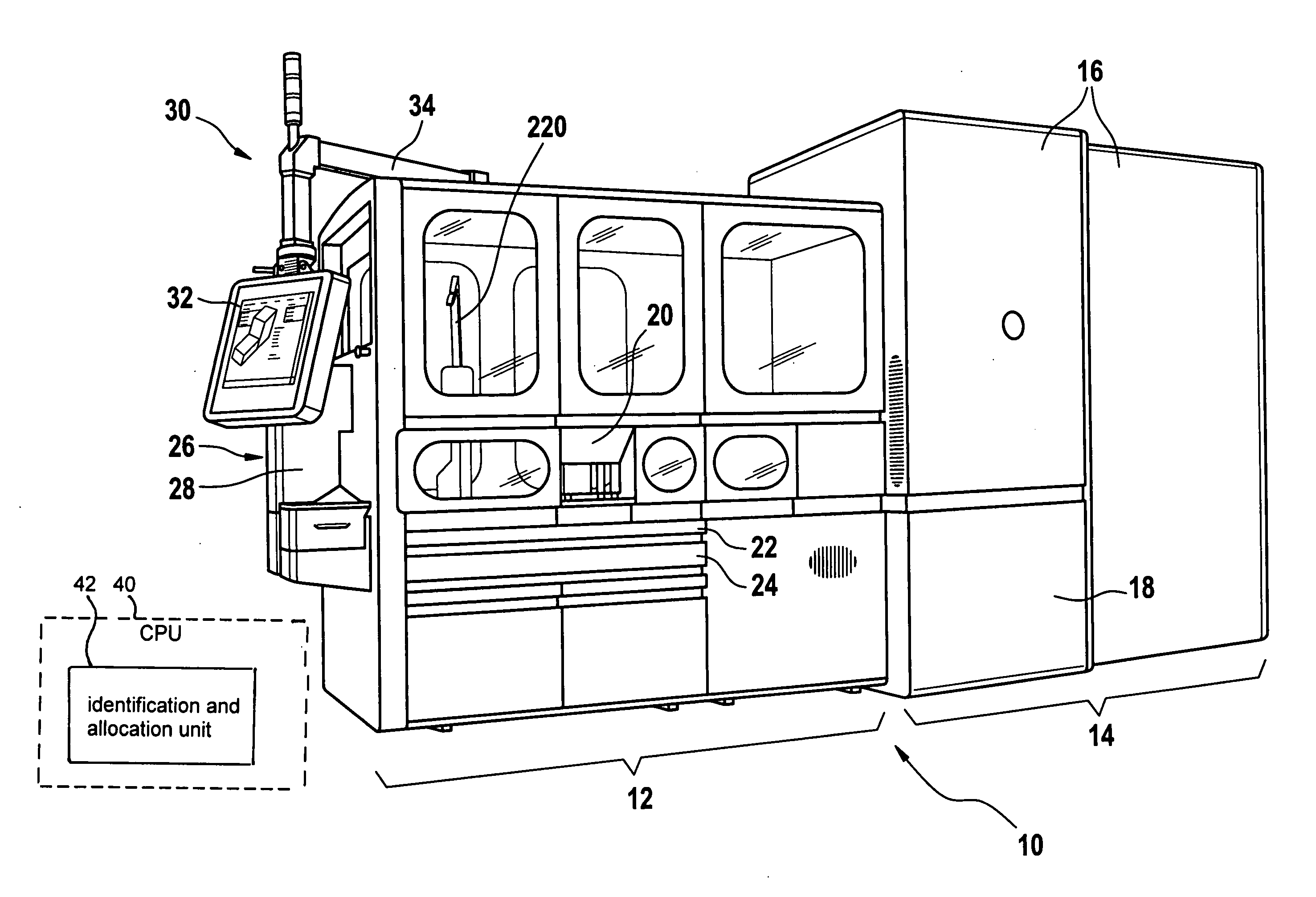
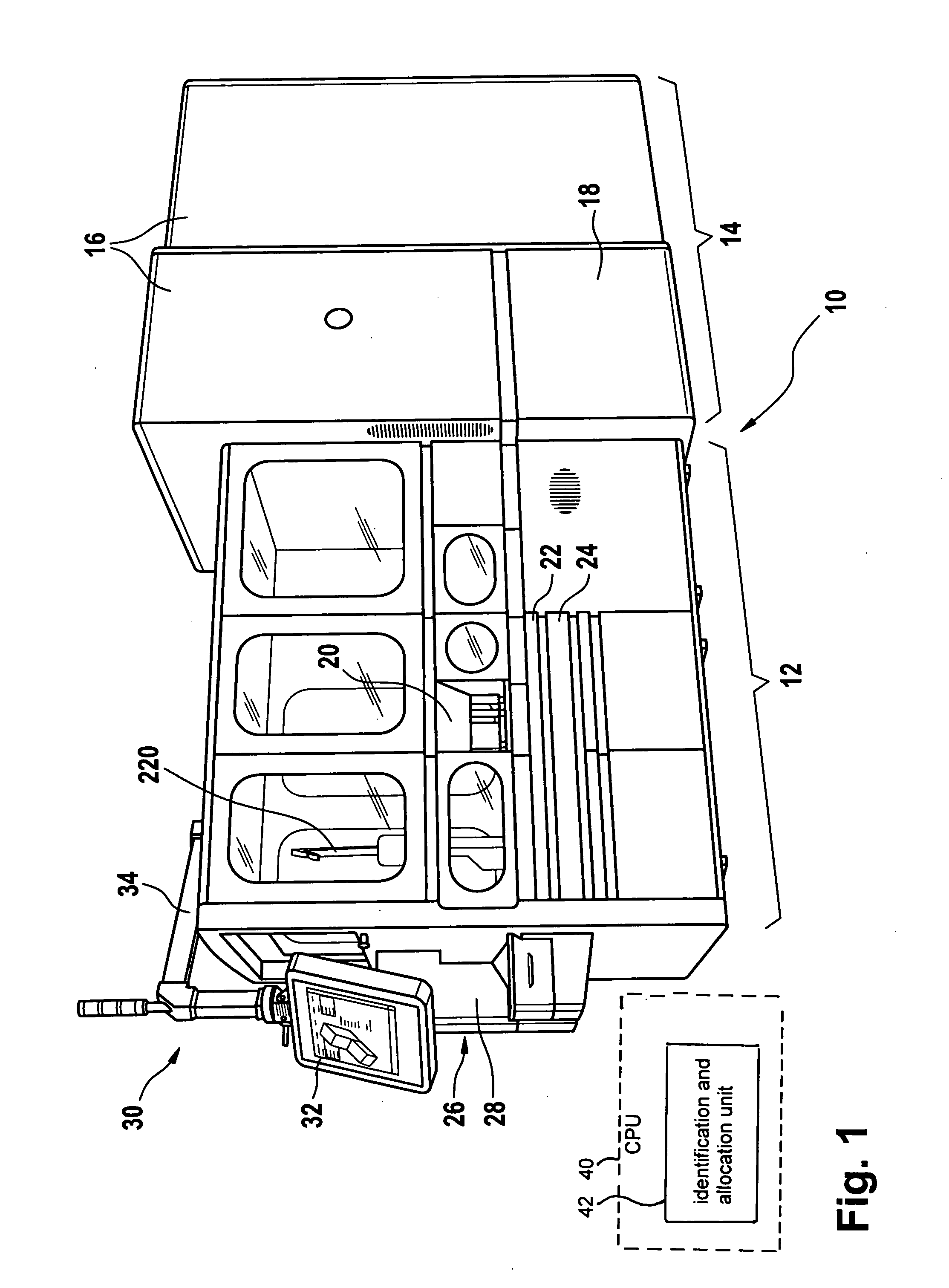
[0026]FIG. 1 shows a perspective view of a laboratory equipment unit 10 comprising a laboratory system in which the invention can be practiced. This laboratory equipment unit 10 may be a so-called storage retrieval module (SRM) forming part of an overall laboratory analyser system. The storage retrieval module comprises a rack handler section 12 (on the left hand side of the depiction of FIG. 1) and a refrigerating or cooling section 14 (on the right hand side of the depiction of FIG. 1). Between the two sections 12, 14 there is a loading / unloading interface (not shown) through which racks are transferred from the the rack handler section 12 into the refrigerating or cooling section 14 and back (in case of retrieval). This loading / unloading inte...


PUM


Abstract

A method and laboratory system for handling sample tubes and an image analysing unit are disclosed. The laboratory system comprises a transfer unit for transferring incoming primary racks (PR) containing sample tubes (S), an image analysing unit (310), and an identification and allocation unit. The method to handle laboratory sample tubes includes steps of: transferring an incoming primary rack (PR) containing sample tubes (S) to the image analysing unit (310); determining, in the image analysing unit (310), geometry parameters of at least one sample tube contained in the primary rack by means of image analysing; comparing for each sample tube the determined geometry parameters with predetermined geometry criteria and identifying whether the sample tube's geometry fulfils the predetermined criteria; in case of fulfilment, categorising the sample tube as system conform; otherwise categorising the sample tube as non-system conform. Each sample tube identified as system conform is entered into further processing and each sample tube identified as non-system conform is entered into error processing.

Description

TECHNICAL FIELD[0001]The present invention relates to the handling of sample tube racks in a test laboratory environment, and particularly to a laboratory device for handling sample tubes in the context of storing such sample tubes in a storage compartment. More particularly, the present invention relates to an automated tubes identification system.DESCRIPTION OF THE RELATED ART[0002]In laboratories, such as for example clinical laboratories in which patient samples are examined and submitted to various in-vitro diagnosis tests, test tubes containing samples (such as blood, urine, etc.) have to be handled in high number and in a cautious but still efficient manner. For years now, automated procedures with corresponding systems and devices have been used in this context.[0003]One aspect during the handling of these sample tubes relates to the tubes being placed in a storage compartment, which can be, for example, a refrigerating device. For efficient handling purposes, the tubes are ...

Claims


Application Information

Patent Timeline
IPC IPC(8): G01N1/00G06K9/00
CPCG01N35/00732G01N35/028G01N35/04G01N2035/0425Y10T436/114165G01N35/0099G01N35/02Y10T436/11G01N35/00594
Inventor MARTY, CHRISTIANRINDERKNECHT, MARKUS
Owner ROCHE DIAGNOSTICS OPERATIONS INC
Why Eureka
Try Eureka