Method and apparatus for in-situ radiofrequency heating

a radiofrequency heating and in-situ technology, applied in the direction of fluid removal, insulation, borehole/well accessories, etc., can solve the problems of difficult recovery and transportation, viscosity, pour point, specific gravity of oil, etc., to improve the recovery and handling of heavy crude oil

Inactive Publication Date: 2011-02-22
TURBOSHALE INC
View PDF11 Cites 147 Cited by
  • Summary
  • Abstract
  • Description
  • Claims
  • Application Information

AI Technical Summary

Benefits of technology

[0013]The present invention provides a system and method to apply radiofrequency energy to in-situ heavy crude oil to heat the oil and other materials in its vicinity. This system and method enhance the recovery of the heavy crude oil. At the same time, it may be used to upgrade the heavy crude oil in situ.
[0014]This system enhances the recovery of oil through a thermal method. Heavy crude oils have high viscosities and pour points, making them difficult to recover and transport. Heating the oil, however, lowers the viscosity, pour point, and specific gravity of the oil, rendering it easier to recover and handle. Thus, in the present invention, directed radiofrequency radiation and absorption are used to heat heavy oil and reduce its viscosity, thus enhancing recovery. This dielectric heating also tends to generate fissures and controlled fracture zones in the formation for enhanced permeability and improved flow recovery of fluids and gases.
[0015]The system of the present invention is an in-situ radiofrequency reactor (RFR) to apply radiofrequency energy to heavy crude oil in situ. The RFR incorporates an in-situ configuration of horizontal and vertical wells in a heavy crude oil field. Using these wells, the RFR creates a subterranean reactor for the optimum production and surface recovery of the heavy crude oil. The RFR will provide an oil / hydrocarbon vapor front that will optimize recovery of the oil.
[0018]The present invention has several promising advantages over present methods used to enhance recovery of heavy oil. In particular, the RFR does not require the use of water from external sources. This reduces expense and makes the recovery more economical and efficient. Furthermore, the present invention does not require the use of expensive solvents. Through the use of the present invention, enhanced recovery of heavy crude oil can be achieved more efficiently and cost-effectively.
[0019]Furthermore, in situ processing of crude oil has several advantages over conventional oil surface upgrading technology. First, in situ upgrading can be applied on a well to well basis, so that large volumes of production needed for surface processes are not required. Large, costly pressure vessels are not required since the reservoir formation serves as a reactor vessel. It can be applied in remote locations where a surface refinery would be inappropriate. Some of the required gases and possibly water can be generated in situ by the radiofrequency energy absorption. Finally, full range whole crude oils are treated by RFR and not specific boiling range fractions as is commonly done in refineries. This is made possible by the ability of radiofrequency absorption to provide precise temperature control throughout the reactor volume. The proposed reactor provides large quantities of heat through radiofrequency absorption close to the production well where the catalyst bed is placed. No heat carrying fluids are necessary with radiofrequency heating.
[0034]Controlling the radiofrequency generator to provide radiofrequency energy to the radiofrequency antenna, including controlling the phasing of the radiofrequency energy emitted.

Problems solved by technology

Heavy crude oils have high viscosities and pour points, making them difficult to recover and transport.
Heating the oil, however, lowers the viscosity, pour point, and specific gravity of the oil, rendering it easier to recover and handle.
The resulting reduction in the viscosity of the oil and mild cracking of the oil causes the oil to drain due to gravity.

Method used


Image

  • Method and apparatus for in-situ radiofrequency heating
  • Method and apparatus for in-situ radiofrequency heating
  • Method and apparatus for in-situ radiofrequency heating

Examples


Embodiment Construction

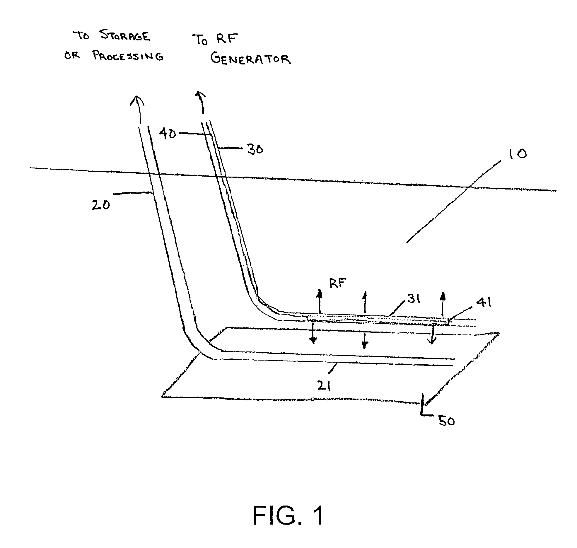
[0043]A variety of different arrangements of wells and antennae may be employed to apply radiofrequency energy to heavy crude oil in situ, thereby enhancing oil recovery and achieving in situ upgrading of the oil. The proper structure and arrangement for any particular application depends on a variety of factors, including size of field, depth, uniformity, and nature and amount of water and gases in the field.

[0044]FIG. 1 is a perspective view of a basic in situ radiofrequency reactor. Heavy oil is present in oil field 10. Oil / gas production well 20 is drilled into the oil field for recovery of heavy oil and other materials. At least a portion of oil / gas production well 20 is drilled horizontally through the oil field. Horizontal oil / gas production well 21 is positioned to receive oil and other gas that are moved or generated by the action of the radiofrequency reactor. A second well, radiofrequency well 30, is drilled into the oil field in proximity to oil / gas production well 20. A...


PUM


Abstract

A radiofrequency reactor for use in thermally recovering oil and related materials includes a radiofrequency antenna configured to be positioned within a well, where the well is provided within an area in which crude oil exists in the ground. The radiofrequency antenna includes a cylindrically-shaped radiating element for radiating radiofrequency energy into the area in which crude oil exists. The cylindrically-shaped radiating element is configured to allow passage of fluids there through. The radiofrequency reactor also includes a radiofrequency generator electrically coupled to the radiofrequency antenna. The radiofrequency reactor is operable to control the radiofrequency energy generated.

Description

CROSS-REFERENCE TO RELATED APPLICATION(S)[0001]This application claims priority from U.S. provisional patent application No. 60 / 692,112, which was filed on Jun. 20, 2005, and which is incorporated herein by reference in its entirety. This application is a continuation of, and claims priority to, U.S. application Ser. No. 12 / 259,828, filed Oct. 28, 2008, which is a continuation-in-part application of, and claims priority to, U.S. application Ser. No. 11 / 471,276, filed Jun. 20, 2006, and now allowed, and which is incorporated herein by reference in its entirety.FIELD OF THE INVENTION[0002]The present invention relates generally to the use of radiofrequency energy to heat heavy crude oil or both heavy crude oil and subsurface water in situ, thereby enhancing the recovery and handling of such oil. The present invention further relates to methods for applying radiofrequency energy to heavy oils in the reservoir to promote in situ upgrading to facilitate recovery. This invention also rela...

Claims


Application Information

Patent Timeline
Patent Type & Authority Patents(United States)
IPC IPC(8): E21B43/00E21B36/00
CPCE21B43/003E21B43/2408E21B43/2401
Inventor KASEVICH, RAYMOND S.
Owner TURBOSHALE INC
Why Eureka
Try Eureka