Light adjustment device and method of LED (Light Emitting Diode) high-voltage direct current centralized power supply system

A centralized power supply, high-voltage DC technology, applied in electric light sources, lighting devices, lamp circuit layouts, etc., can solve problems such as individual dimming, and achieve the effects of improving luminous efficiency, convenient dimming, and simple structure

Active Publication Date: 2013-10-23
SOUTH CHINA UNIV OF TECH +1
View PDF4 Cites 6 Cited by
  • Summary
  • Abstract
  • Description
  • Claims
  • Application Information

AI Technical Summary

Problems solved by technology

However, the existing dimming technologies only have one dimming method, that is, only individual dimming can be realized, or only unified dimming can be realized.

Method used


Image

  • Light adjustment device and method of LED (Light Emitting Diode) high-voltage direct current centralized power supply system
  • Light adjustment device and method of LED (Light Emitting Diode) high-voltage direct current centralized power supply system
  • Light adjustment device and method of LED (Light Emitting Diode) high-voltage direct current centralized power supply system

Examples


Embodiment 1

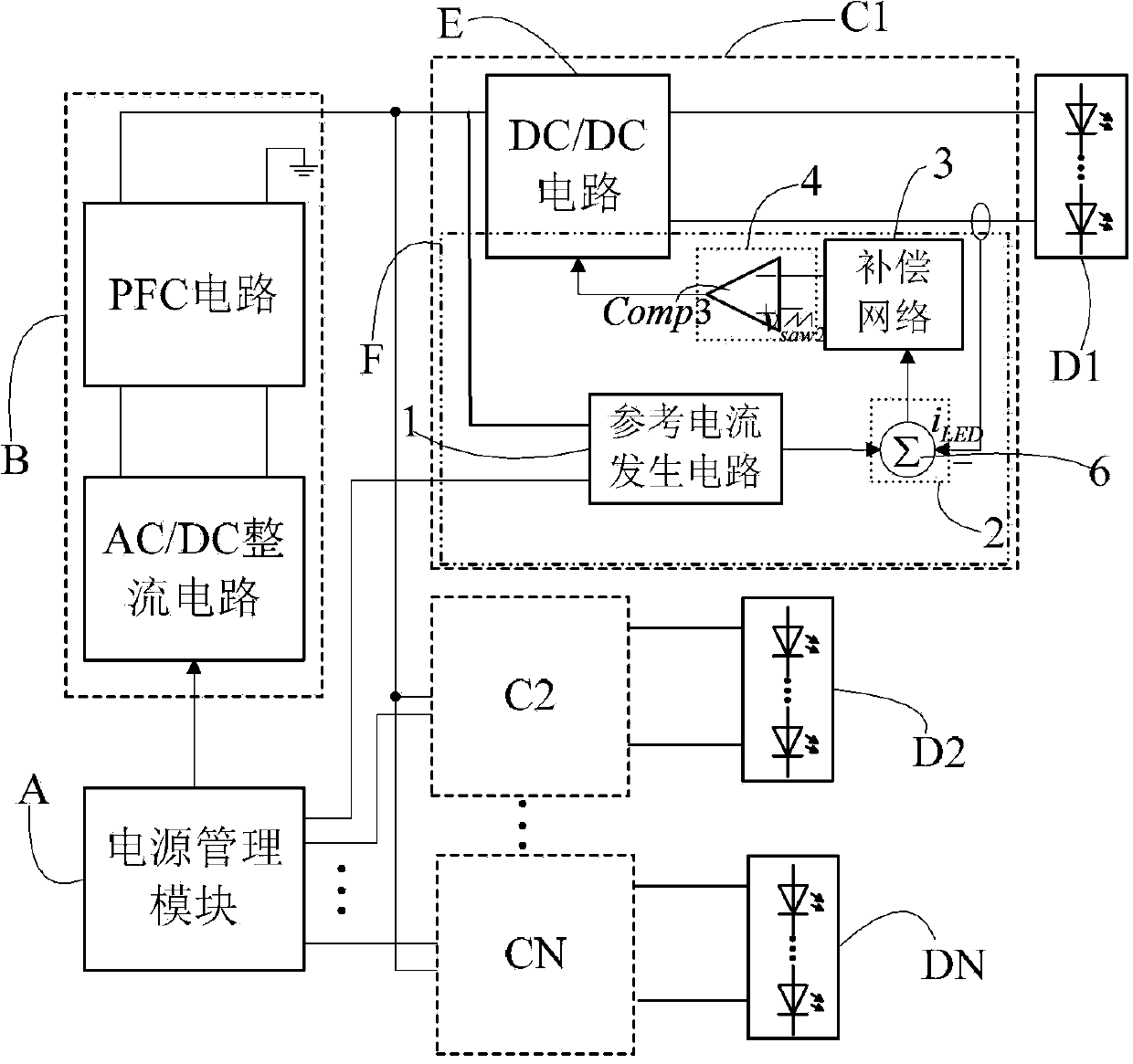
[0031] Such as figure 1 As shown, a dimming device for an LED high-voltage DC centralized power supply system includes a power management module A, a DC power supply module B, and N current regulation modules C 1 ,C 2 ,...C N and N loads D 1 ,D 2 ,...D N , the N≥1, the output terminal of each current regulation module is connected to the load.

[0032] The power supply module control signal output terminal of the power management module A is connected to the control signal receiving terminal of the DC power supply module B, and the positive output terminal of the DC power supply module B and the sawtooth wave signal v of the power management module A saw1 The output terminals are respectively connected with N current regulation modules C 1 ,C 2 ,...C N The input terminal of the DC power supply module B is connected to the ground, and the output terminal of each current regulation module is connected to the load.

[0033] The DC power supply module B is composed of a P...

Embodiment 2

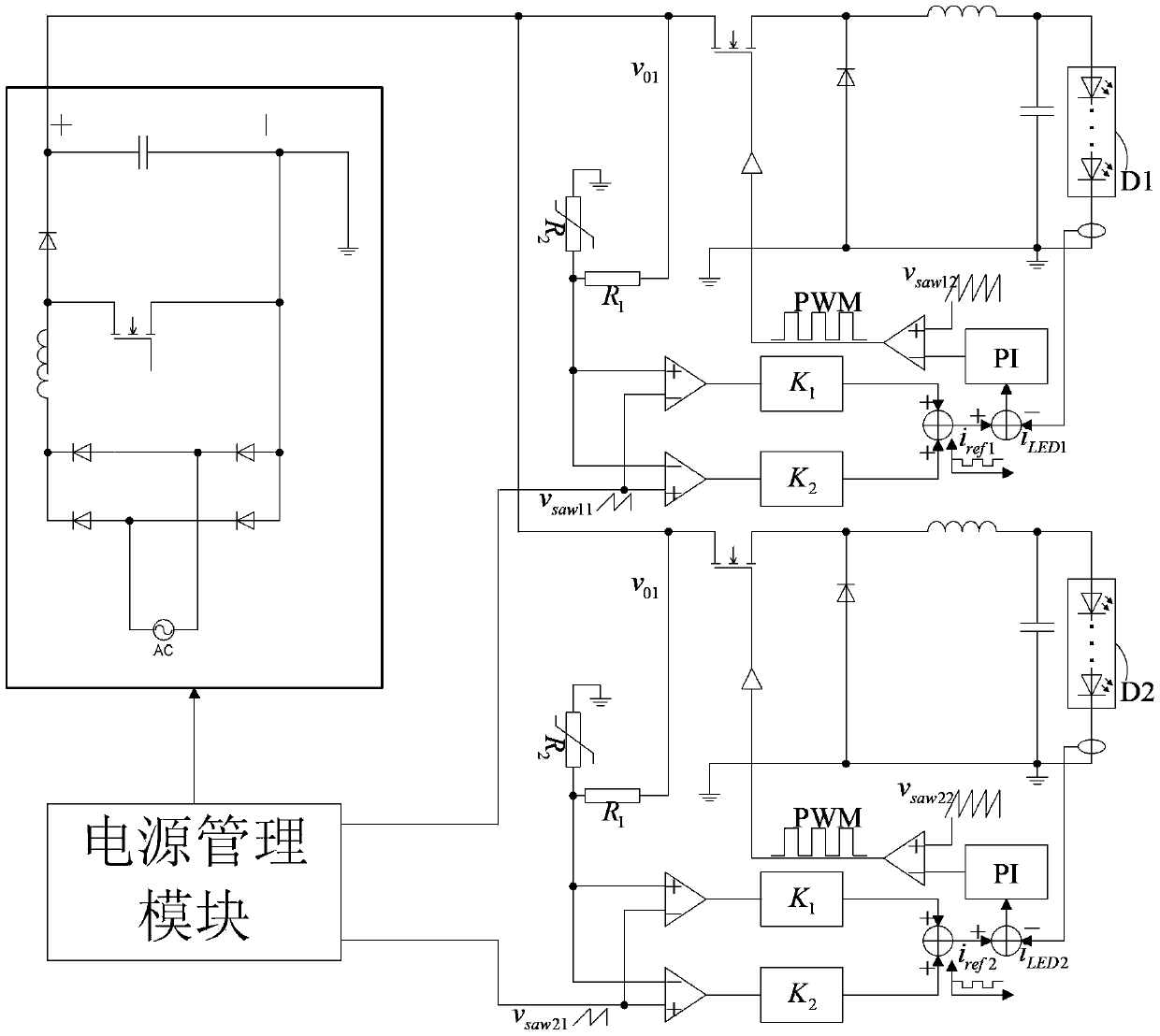
[0046] Connect the circuit as shown in Example 1, as image 3 As shown, there are two current regulation modules in the figure, the two power regulation modules are respectively connected to the load D1 and the load D2, the high level amplification factor is 2, and the low level amplification factor is 1.5. Such as Figure 4 (a) and (b) show the current waveforms flowing in different loads before dimming. When performing unified dimming, the current waveforms flowing in all LED loads are as follows: Figure 5 As shown in (a) and (b); when performing individual dimming, the current waveforms flowing in different LED loads are as follows Figure 6 (a), (b) shown.

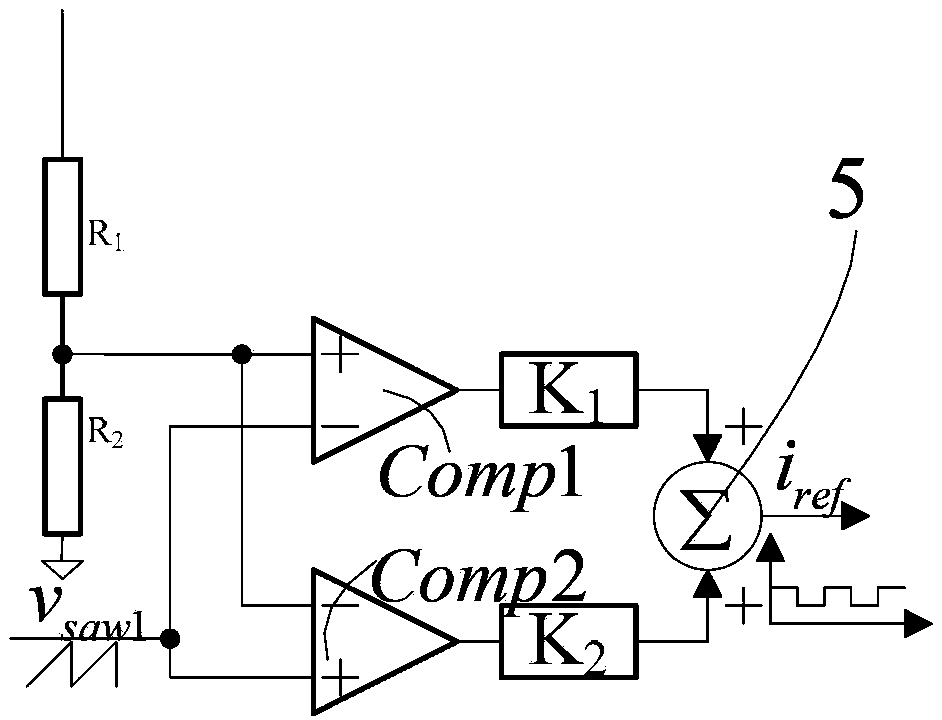
[0047] The present invention adjusts the output voltage of the DC power supply module or adjusts the sawtooth wave signal v saw1 The peak value or cycle of the reference current is changed to change the average value of the current flowing through the LED load within a cycle to achieve LED brightness adjustment.


PUM


Abstract

The invention discloses a light adjustment device and method of an LED (Light Emitting Diode) high-voltage direct current centralized power supply system. The light adjustment device comprises a power source management module, a direct-current power supply module and N electric current adjustment modules, wherein N is greater than or equal to 1, the power source management module is connected with the control signal receiving end of the direct-current power supply module, the input ends of the N electric current adjustment modules are respectively connected with the positive output end of the direct-current power supply module, the negative output end of the direct-current power supply module is grounded, and the output end of each electric current adjustment module is connected with a load. The light adjustment device has the advantages that the unified light adjustment of multiple loads is realized by adjusting the output voltage value of the direct-current power supply module; and the independent light adjustment of each LED load is realized by adjusting sawtooth signals (vsaw1) in each electric current adjustment module. When a multi-level driving technology is adopted by the light adjustment device, the light emitting efficiency of LEDs is improved, and the long service life of the LED loads is ensured.

Description

technical field [0001] The invention relates to the technical field of semiconductor lighting applications, in particular to a dimming device and method for an LED high-voltage direct current centralized power supply system. Background technique [0002] With the continuous development of the LED lighting industry, the application fields of LED lighting are becoming more and more extensive. LED street lighting is one of the important application fields. LED centralized power supply technology is a technology that is very suitable for the field of street lighting. Although sufficient brightness is required in the field of street lighting, appropriately reducing the brightness in the time period with few people and increasing the brightness in the time period with many people can not only ensure that the brightness meets the demand, but also play a role in energy saving. In LED street lighting The above purpose can be achieved by adding the dimming function to the system. [...

Claims


Application Information

Patent Timeline
Patent Type & Authority Applications(China)
IPC IPC(8): H05B37/02
Inventor 张波张能黄子田肖文勋丘东元
Owner SOUTH CHINA UNIV OF TECH
Why Eureka
Try Eureka