Magnetic separation device

A technology of magnetic separation device and magnetic separation column, which is applied in magnetic separation, high-gradient magnetic separator, solid separation, etc., and can solve problems such as inability to separate magnetic particles

Inactive Publication Date: 2013-10-23
KK TOSHIBA
View PDF12 Cites 12 Cited by
  • Summary
  • Abstract
  • Description
  • Claims
  • Application Information

AI Technical Summary

Problems solved by technology

[0005] However, in the existing magnetic separation device, it i...

Method used


Image

  • Magnetic separation device
  • Magnetic separation device
  • Magnetic separation device

Examples


Embodiment Construction

[0017] Hereinafter, the magnetic separation device according to the embodiment will be described with reference to the drawings.

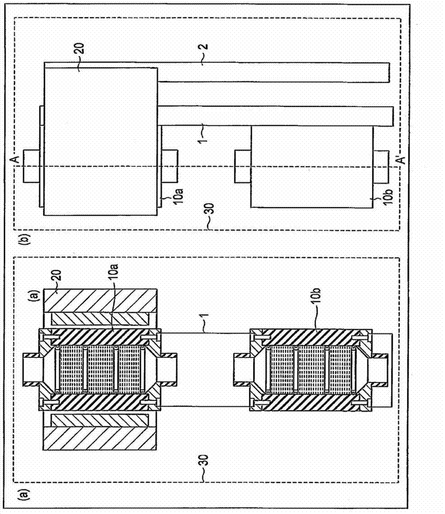
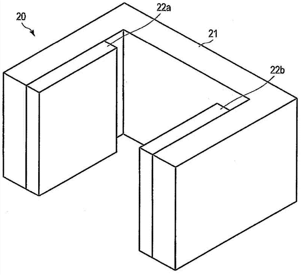
[0018] figure 1 (a) is a front view showing a partial cross section of the magnetic separation device according to the embodiment, figure 1 (b) is a side view. exist figure 1 (a) is shown along the figure 1 (b) The section obtained by cutting along the A-A' line. Such as figure 1 As shown in (a) and (b), the first and second magnetic separation columns 10a, 10b are fixed on the column support table 1 erected in the vertical direction in such a way that they are located on the same straight line in the vertical direction, and In-line configuration. Such as figure 1 As shown in the side view of (b), the magnetic field application device support base 2 is erected vertically behind the column support base 1 . The magnetic field applying device 20 is attached to the magnetic field applying device supporting stand 2 so as to slide along the magne...


PUM


Abstract

This embodiment of a magnetic separation device has: a plurality of magnetic separation columns of which a plurality are disposed in series and that have a plurality of filters comprising a non-magnetic cylinder of which the hollow center is the flow path for water to be processed, and a magnetic body disposed in a manner so as to be perpendicular to the flow of water to be processed within the cylinder; and a magnetic field imposition device that imposes a magnetic field to a portion of the magnetic separation columns, has a size that corresponds to the portion of magnetic separation columns, and is provided slidably to the outside of the plurality of magnetic separation columns.

Description

technical field [0001] Embodiments of the present invention relate to magnetic separation devices. Background technique [0002] Magnetic particles such as iron powder are contained in waste liquid discharged from metal processing factories and ironworks. In order to separate magnetic particles from such waste liquid, a magnetic separator using a magnet is used. [0003] For example, there is known a magnetic separation device having a pipe through which waste liquid containing magnetic particles passes, a filler made of a magnetic substance arranged in the pipe, and a magnet arranged on the outer periphery of the pipe to apply a magnetic field to the filler. In such a magnetic separator, when the waste liquid passes through the pipe, a magnetic field is applied to the filler by a magnet arranged on the outer periphery of the pipe, and the magnetic particles are captured by the filler to separate the magnetic particles from the waste liquid. There are mesh form, fibrous fo...

Claims


Application Information

Patent Timeline
IPC IPC(8): B03C1/025B03C1/00B03C1/032B03C1/034
CPCB03C2201/18B03C1/288B03C1/035
Inventor 深谷太郎山崎厚山梨伊知郎早见德介木内智明
Owner KK TOSHIBA
Why Eureka
Try Eureka