DIN-rail mount type device

A technology of rails and sliders, applied in the directions of support structure installation, elastic/clamping device, circuit layout on support structure, etc., can solve problems such as inability to place DIN rail mounted devices horizontally, damage to locking members, etc.

Active Publication Date: 2013-11-06
YASKAWA DENKI KK
View PDF3 Cites 13 Cited by
  • Summary
  • Abstract
  • Description
  • Claims
  • Application Information

AI Technical Summary

Problems solved by technology

Also, there is a problem that the locking member is damaged when transporting the DIN rail-mounted device, or that the DIN-rail mounted device cannot be placed horizontally with the locking member side down

Method used


Image

  • DIN-rail mount type device
  • DIN-rail mount type device
  • DIN-rail mount type device

Examples


Embodiment Construction

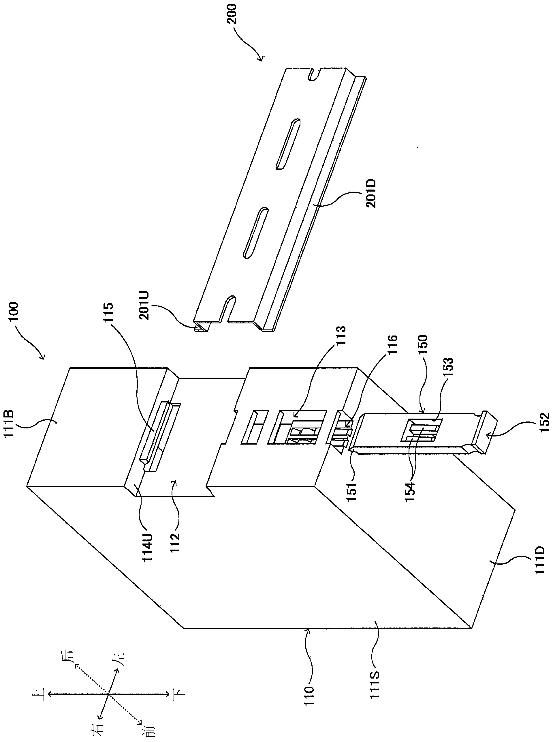
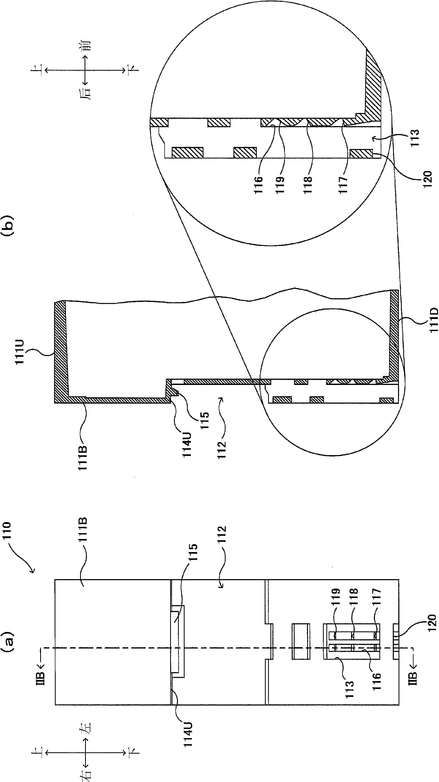
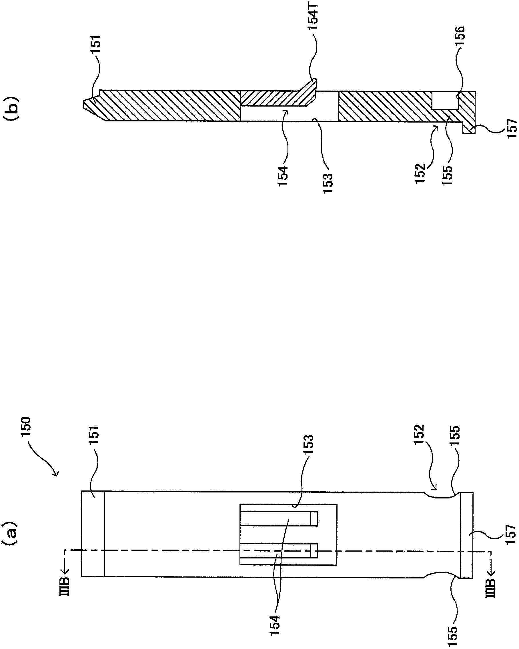
[0021] Embodiments will be described below with reference to the drawings. When referring to "front", "rear", "left", "right", "upper" and "lower" in the following figures, "forward", "backward", " Left", "Right", "Up", and "Down" to denote the pointed direction.

[0022] exist figure 1 , figure 2 (a), (b) of and image 3 In (a) and (b), the DIN rail-mounted device 100 according to the present embodiment refers to a DIN rail 200 that is removably mounted on a DIN standard (Deutsche Industries Noemen: German Industrial Standard) on the device. For example, control devices such as controller units, PLC (programmable logic controller) units, inverter units, servo units, power supply units, I / O units, sensor units, switch units, safety units, and relay units can be employed as DIN rail mountable device 100 . Alternatively, devices other than control devices may be employed. Such as figure 1 As shown, DIN rail mountable device 100 includes a front surface (not shown) as a ...


PUM


Abstract

In order to enable a locking member to be housed without protruding from a case, a DIN-rail mount type device (100) is equipped with a case (110), a rail groove (112) that can be fitted to a DIN rail (200), a slider groove (113), and a locking member (150). The locking member (150) is configured such that the locking member can be moved between a locked position at which the engagement-side end section (151) protrudes into the rail groove (112) from the slider groove (113) and the manipulation-side end section (152) protrudes from the case (110), and a housed position at which the engagement-side end section (151) protrudes into the rail groove (112) from the slider groove (113) and the manipulation-side end section (152) is housed inside the slider groove (113); the fitted state of the rail groove (112) and the DIN rail (110) can be maintained by letting the engagement-side end section (151) engage with the lower engagement piece section (201D) of the DIN rail (200) at the locked position; and the movement to the housed position is enabled only when the DIN rail (110) is not fitted to the rail groove (112).

Description

technical field [0001] The disclosed embodiments relate to a DIN rail mounted device that is removably mounted on a DIN rail. Background technique [0002] A DIN rail-mounted device that is removably mounted on a DIN rail is known in the prior art (for example, refer to Patent Document 1). The case (unit body) of the prior art DIN rail mountable device (programmable controller unit) includes a rail groove (engagement recess) provided at the back of the case along the width of the case Extending in the direction, the housing engages with the DIN rail via the rail groove, and is locked on the DIN rail by means of a locking member (slider locking device) to be mounted on the DIN rail. [0003] prior art literature [0004] patent documents [0005] Patent document 1JP3453739B Contents of the invention [0006] The problem to be solved by the present invention [0007] In the above-mentioned prior art DIN rail mount type device, the locking member protrudes out of the hou...

Claims


Application Information

Patent Timeline
Patent Type & Authority Applications(China)
IPC IPC(8): H05K7/12
CPCH02B1/0523H02B1/052H05K5/0204H05K7/12H05K7/14
Inventor 久住道德上杉肇宗广直人
Owner YASKAWA DENKI KK
Why Eureka
Try Eureka