
Ergonomic tool handle enhancement

A tool handle and handle technology, applied in the field of ergonomic tool handles, can solve problems such as the inability to reduce arm fatigue

Inactive Publication Date: 2013-11-20
SUPREME INVENTION
View PDF12 Cites 1 Cited by
  • Summary
  • Abstract
  • Description
  • Claims
  • Application Information

AI Technical Summary

Problems solved by technology

[0009] A drawback of the prior art is that the user does not have enough arm fatigue or assistance to maintain adequate control of the tool through the various rings or ring attachments

Method used


Image

  • Ergonomic tool handle enhancement
  • Ergonomic tool handle enhancement
  • Ergonomic tool handle enhancement

Examples


Embodiment Construction

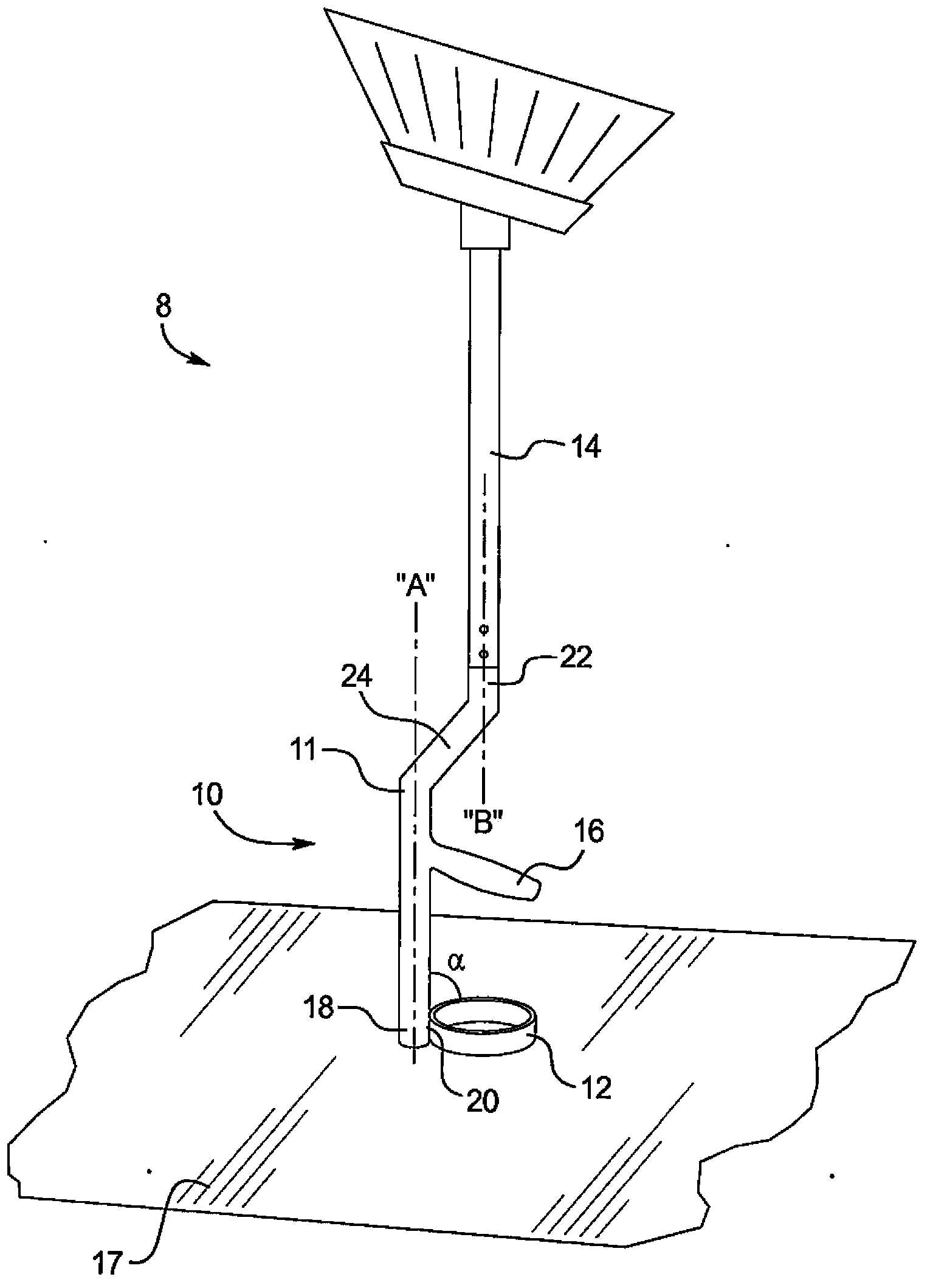
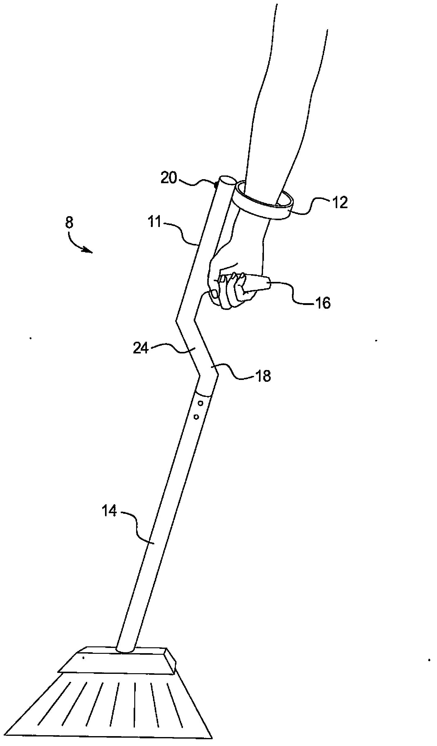
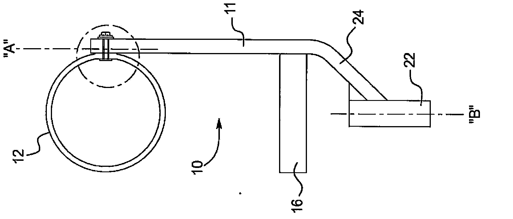
[0047] refer to figure 1 , tool 8 is generally selected as a broom, although other tools are contemplated including, but not limited to, snow shovels, rakes, saws, hammers, lawn and hedge trimmers, scrapers, and other power tools or non-power hand tools. The ergonomic tool handle is shown generally at 10 and includes a separate crossbar 11 and an armband 12 rotatably connected to the crossbar. Attached to the ergonomic tool handle 10 is a post-type or rod-type tool handle member 14, such as a broom or rake, which also preferably has a handle 16 extending generally transversely from the crossbar 11. The tool 8 is shown upside down from the normal use position and supported on the base 17 . The crossbar 11 includes a free end 18 at which the armband 12 is rotatably disposed at a connection point 20 ( image 3 better seen), also includes the opposite working end 22, the working end 22 is associated with the tool handle assembly 14.

[0048] In a preferred embodiment, the hand...


PUM

PropertyMeasurementUnit
diameteraaaaaaaaaa
diameteraaaaaaaaaa

Abstract

The invention discloses a tool handle including: a body configured to receive a handle of a tool; a hand grip extending approximately perpendicular from the body; and an arm ring rotatably disposed on the body, wherein the arm ring is adapted to be placed in at least two positions, a first position in which the arm ring is generally perpendicular to the hand grip such that a user may place the users forearm through the arm ring to grasp the hand grip and a second position in which the arm ring is generally parallel to the hand grip so as to minimize the width of the tool handle.

Description

[0001] Cross References to Related Applications [0002] This application claims priority to U.S. Provisional Patent Application No. 61 / 422,811 filed December 14, 2010 and U.S. Provisional Patent Application No. 61 / 524,3141 filed August 16, 2011 right, and is hereby incorporated by reference. technical field [0003] The present invention generally relates to a tool handle strengthener that can be adapted for use with a wide variety of tools including brooms, shovels, rakes and power tools. More particularly, it relates to an ergonomic tool handle for relieving strain on the operator's wrist, elbow and / or back. Background technique [0004] A traditional broom, rake, or similar implement, especially those with long cylindrical handles, that requires the user to maneuver the implement with the wrists, arms, shoulders, and back, such as when broom users do this type of work to sweep up debris Pile up, places that are difficult to access, such as under a table or in a corner...

Claims


Application Information

Patent Timeline
Patent Type & Authority Applications(China)
IPC IPC(8): B25G3/02B25G3/04B25G3/26B25G1/10
CPCA47L13/08A01B1/00B25G1/102A01B1/22Y10S16/901
Inventor S·K·李
Owner SUPREME INVENTION
Learn More