Hermetically sealed rotary compressor

A rotary compressor and rotary compression technology, applied in rotary piston machines, rotary piston pumps, rotary piston/oscillating piston pump components, etc., can solve problems such as failure of electric components and melting of sliding parts

Active Publication Date: 2013-11-27
SANYO ELECTRIC CO LTD
View PDF8 Cites 0 Cited by
  • Summary
  • Abstract
  • Description
  • Claims
  • Application Information

AI Technical Summary

Problems solved by technology

If the temperature rises abnormally, the failure of the ...

Method used


Image

  • Hermetically sealed rotary compressor
  • Hermetically sealed rotary compressor
  • Hermetically sealed rotary compressor

Examples


Embodiment Construction

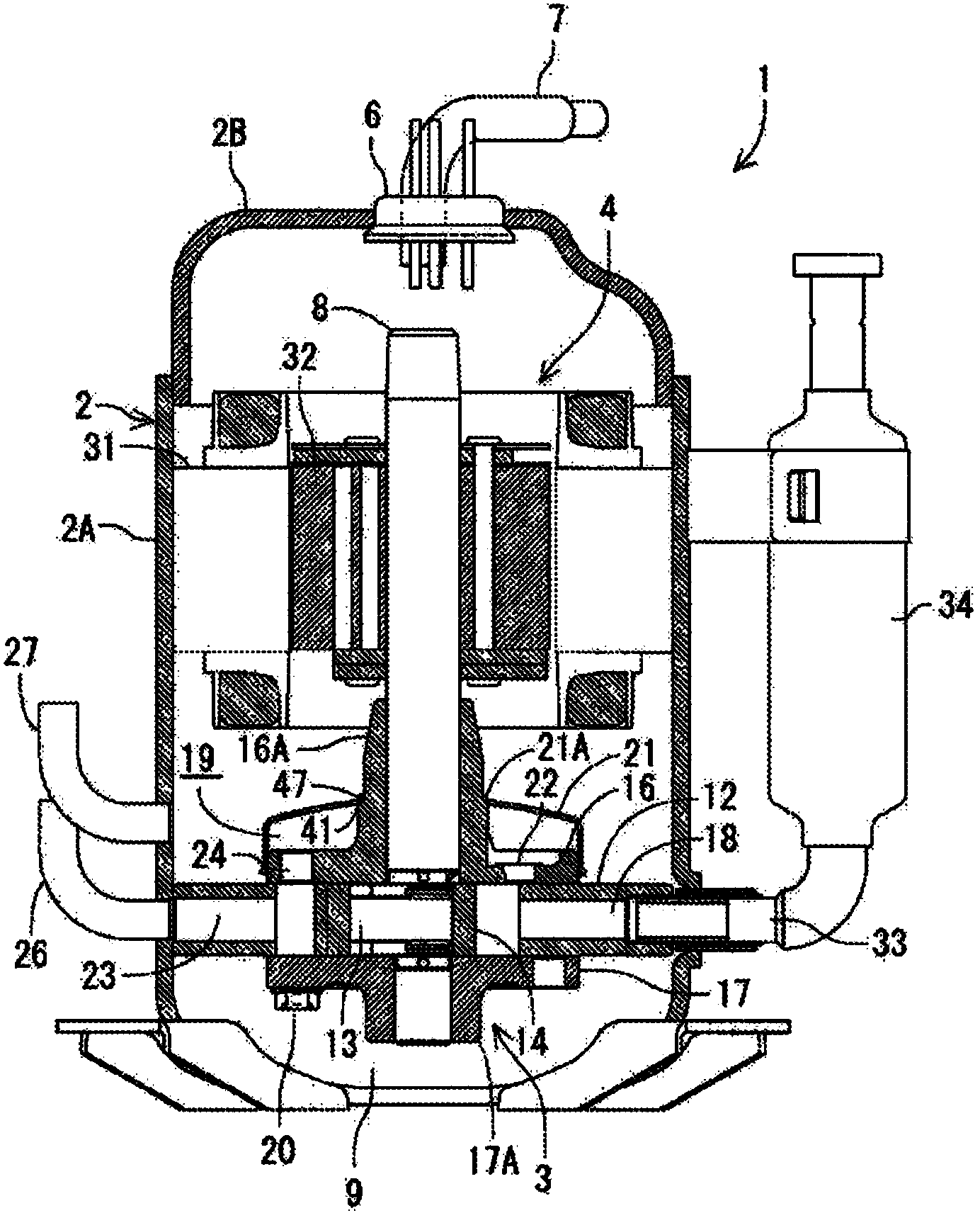
[0029] Hereinafter, embodiments of the present invention will be described in detail with reference to the drawings. In the hermetic rotary compressor 1 of the embodiment, the electric element 4 is housed in the upper part of the internal space of the vertical cylindrical airtight container 2 made of steel plate, and the rotary shaft 8 driven by the electric element 4 is housed in the lower part. A rotary compressor formed by compressing the element 3 .

[0030] The airtight container 2 is composed of a container body 2A and a roughly bowl-shaped end cap (cover) 2B. The container body 2A accommodates the electric element 4 and the rotary compression element 3. The end cap 2B closes the upper opening of the container body 2A. On the upper surface of the end cover 2B, a terminal (wiring is omitted) 6 for supplying electric power to the electric element (motor) 4 positioned above the inside of the airtight container 2 is attached. Further, a coolant discharge pipe 7 communicatin...


PUM


Abstract

[Problem] To provide a hermetically sealed rotary compressor configured so that the joint between a cup and a bearing can be sealed without the use of a ring, etc. [Solution] An upper bearing (16A) has a stepped section (41), and the corner of the stepped section (41) is chamfered to form a chamfered section (41A). The inner edge of a cup (21) is curved at a predetermined curvature to form a curved section (47). The curved section (47) is in contact with the chamfered section (41A) of the stepped section (41). The bolt affixation section (44) of the cup (21) before the cup (21) is affixed by a bolt to an upper support member (16) while the curved section (47) is made to be in contact with the stepped section (41) is sized so that the bolt affixation section (44) is separated from the upper support member (16).

Description

technical field [0001] The present invention relates to a hermetic rotary compressor in which an electric element and a rotary compression element are accommodated in an airtight container. Background technique [0002] Conventionally, such hermetic rotary compressors are constructed by accommodating an electric element (electric motor) and a rotary compression element driven to rotate by a rotary shaft of the electric element in an airtight container. The rotary compression element is usually composed of a cylinder, a roller, a blade, an upper supporting part and a lower supporting part in a vertical case. Rotating eccentrically in the cylinder, the blades contact the rollers to divide the cylinder into a low-pressure chamber side and a high-pressure chamber side. The upper and lower support members close the upper and lower opening surfaces of the cylinder and have bearings for the rotating shaft. [0003] In addition, the cover is fixed to the upper surface of the upper ...

Claims


Application Information

Patent Timeline
IPC IPC(8): F04C29/06F04C18/356F04C27/00
CPCF04C2230/60F04C27/008F04C23/008F01C21/10F04C18/356
Inventor 斋藤隆泰西川刚弘吉田浩之比留间义明
Owner SANYO ELECTRIC CO LTD
Why Eureka
Try Eureka