
Microwave shrinkage type connection structure of combined structure and construction technology

A composite structure and connection structure technology, which is applied in the direction of load-bearing elongated structural members, structural elements, building components, etc., can solve the problem that the flange plate cannot shrink, affect the overall structural strength of the composite structure, and the peeling of steel plates and concrete and other problems, to achieve the effect of reducing concrete shrinkage cracks and composite structure stress redistribution phenomenon

Active Publication Date: 2013-12-04
ZHEJIANG CTB WAVEFORM STEEL WEB
View PDF8 Cites 3 Cited by
  • Summary
  • Abstract
  • Description
  • Claims
  • Application Information

AI Technical Summary

Problems solved by technology

[0003] The invention aims at the fact that the flange plate made of straight steel plates in the prior art cannot shrink when the concrete shrinks, and also bears the longitudinal compressive stress transmitted when the concrete shrinks. When the concrete is poured, shrinkage and creep occur, resulting in the steel plate and concrete. Shelling phenomenon, even lead to concrete cracks, affecting the overall structural strength of the combined structure and other shortcomings, provides a method by setting micro-strain waves on the flange plate, so that the flange plate and the concrete change synergistically, reducing the shrinkage cracks and shrinkage of the concrete Combination Structure Microwave Shrinkage Connection Structure of Combination Structure Stress Redistribution Phenomenon

Method used


Image

  • Microwave shrinkage type connection structure of combined structure and construction technology

Examples


Embodiment 1

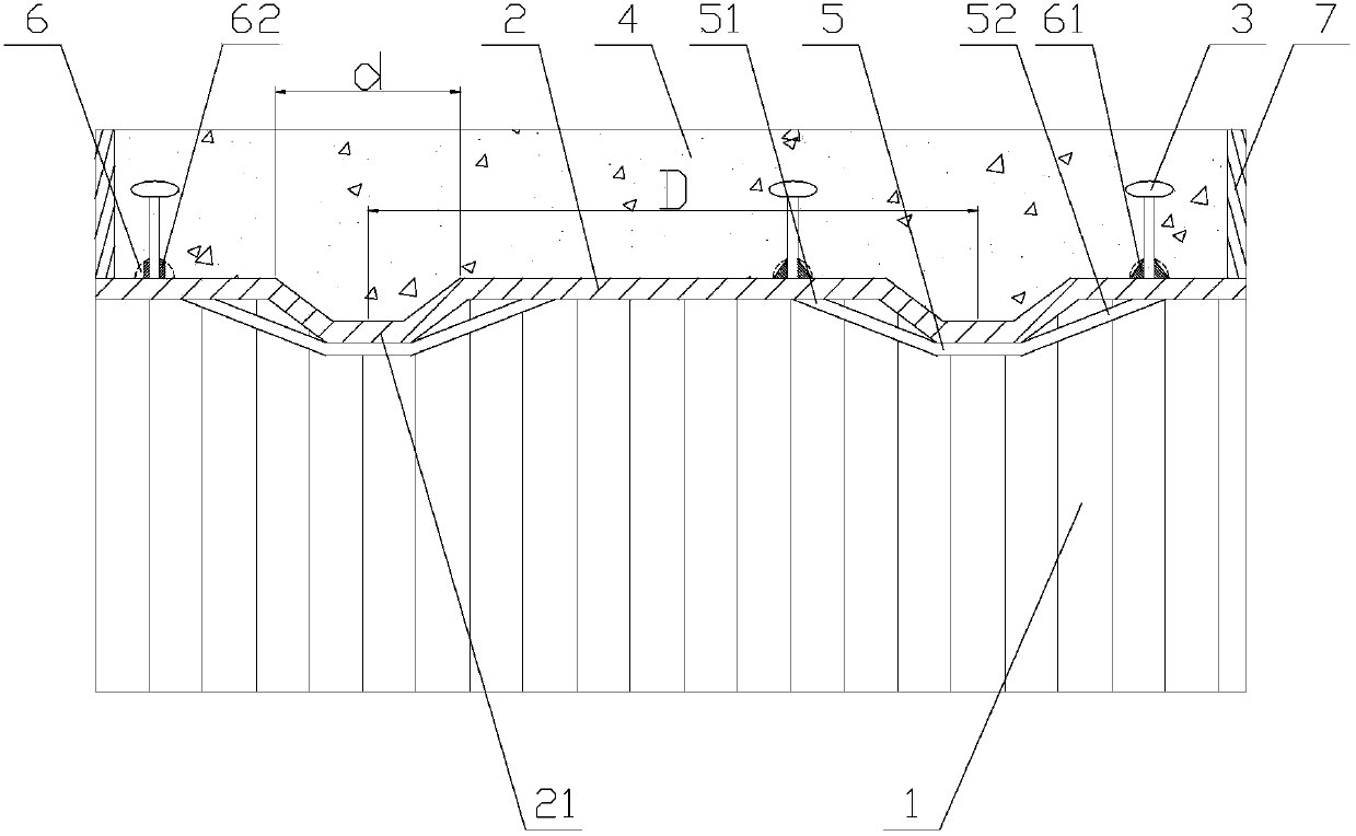
[0022] Combination structure Microwave shrinkage connection structure, such as figure 1 As shown, it includes corrugated steel web 1, flange plate 2, and concrete 4. One side of the flange plate 2 is welded with the corrugated steel web 1, and the other side is combined with concrete 4. The flange plate 2 has micro-strain Wave 21, the roughness of the flange plate 2 is 50-500 μm. Limiting end plates 7 are arranged at both ends of the beam, and by setting micro-shaped strain waves 21 on the flange plate, compared with the straight flange plate in the prior art that cannot shrink longitudinally, the flange with micro-strain wave The plate 2 can shrink together with the concrete in the longitudinal direction, and the corrugated steel plate connected with the flange plate 2 itself has a certain longitudinal shrinkage ability. The whole structure can be coordinatively stressed to achieve a fully combined state.

[0023] The micro-shape strain wave 21 is a micro-strain wave with a...

Embodiment 2

[0030] The difference between this embodiment and embodiment 1 is:

[0031] The micro-shape strain wave 21 is a micro-strain wave with a convex crest, and the wave height of the micro-strain wave 21 is 12 times the thickness of the flange plate 2; The peak length d of the convex portion of the micro-shape strain wave 21 is 180 mm, and the distance D between the peaks of adjacent micro-shape strain waves 21 is 1500 mm.

[0032] The crest of the micro-shape strain wave 21 of the flange plate 2 is closely attached to the contraction connecting plate 5 . The left end 51 and the right end 52 of the contraction connecting plate 5 are welded to the flange plates 2 on both sides of the micro-shape strain wave 21 . The shrinkage stress of welding is used to shrink the micro-shape strain wave 21, so as to achieve the purpose of co-shrinkage of the flange plate 2 and the concrete. In addition, when the shrinkage connecting plate 5 is welded to the flange plate 2 on both sides of the mi...

Embodiment 3

[0036] The difference between this embodiment and embodiment 1 is:

[0037]The micro-shape strain wave 21 is a micro-strain wave with a convex crest, and the wave height of the micro-strain wave 21 is 18 times the thickness of the flange plate 2; The peak length d of the convex part of the micro-strain wave 21 is 210 mm, and the distance D between the peaks of the adjacent micro-strain waves 21 is 2100 mm.

[0038] The micro-shape strain wave 21 is a micro-strain wave with a convex crest, and the wave height of the micro-strain wave 21 is 3-20 times the thickness of the flange plate 2;

[0039] The crest of the micro-shape strain wave 21 of the flange plate 2 is closely attached to the contraction connecting plate 5 . The left end 51 and the right end 52 of the contraction connecting plate 5 are welded to the flange plates 2 on both sides of the micro-shape strain wave 21 . The shrinkage stress of welding is used to shrink the micro-shape strain wave 21, so as to achieve the...


PUM

PropertyMeasurementUnit
Roughnessaaaaaaaaaa

Abstract

The invention relates to a steel and concrete combined structure, and discloses a microwave shrinkage type connection structure of a combined structure and a construction technology. The microwave shrinkage type connection structure comprises a wave-shaped steel web plate (1), a flange plate (2) with micro strain waves (21) and concrete (4), wherein one surface of the flange plate (2) is welded to the wave-shaped steel web plate (1), and the other surface of the flange plate (2) is combined with concrete (4); the roughness of the flange plate (2) is 50-500 micron. The construction technology comprises the steps as follows: A, pressing the micro strain waves (21) of the flange plate (2); B, welding the flange plate (2) to the wave-shaped steel web plate (1); C, performing concrete construction; D, performing concrete curing. According to the invention, since the micro strain waves are arranged on the flange plate, the flange plate and the concrete can be in coordinated change and shrinkage, so that shrinkage cracks of the concrete and stress redistribution of the combined structure are reduced.

Description

technical field [0001] The invention relates to a steel-concrete composite structure, in particular to a microwave shrinkage connection structure and construction technology of the composite structure. Background technique [0002] At present, the concrete in the composite structure has shrinkage and creep, but the connecting key cannot be strained during the shrinkage and creep of the concrete. For example, the flange plate made of a straight steel plate cannot shrink when the concrete shrinks, and it also bears the burden of the concrete shrinkage. When the longitudinal compressive stress is transmitted, when the concrete shrinks and creeps after pouring, since the straight flange plate will not shrink together, it will often lead to shelling of the steel plate and concrete, and even cracks in the concrete. Contents of the invention [0003] The invention aims at the fact that the flange plate made of straight steel plates in the prior art cannot shrink when the concrete...

Claims


Application Information

Patent Timeline
IPC IPC(8): E04C3/293E04G21/00
Inventor 孙天明陆青锋
Owner ZHEJIANG CTB WAVEFORM STEEL WEB
Learn More