
Clamping mechanism

A buckle and chuck technology, which is applied in the direction of connection components, mechanical equipment, thin plate connection, etc., can solve the problems of inconvenient assembly and disassembly with screws, and achieve simple and convenient mechanism, small volume, and reduce redundant operation steps of closing and opening Effect

Active Publication Date: 2013-12-11
BOZHON PRECISION IND TECH CO LTD
View PDF4 Cites 2 Cited by
  • Summary
  • Abstract
  • Description
  • Claims
  • Application Information

AI Technical Summary

Problems solved by technology

[0003] The purpose of the present invention is to provide a buckle mechanism for the deficiencies of the prior art, which can quickly connect and separate the panel and the side panel, thereby greatly improving the inconvenience of using screws to assemble and disassemble, thereby reducing the Reduce production costs and reduce the labor intensity of operators

Method used


Image

  • Clamping mechanism
  • Clamping mechanism

Examples


Embodiment Construction

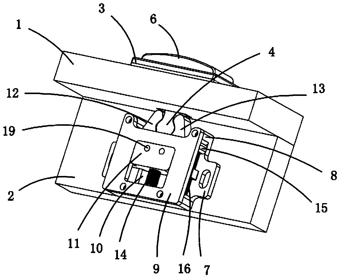
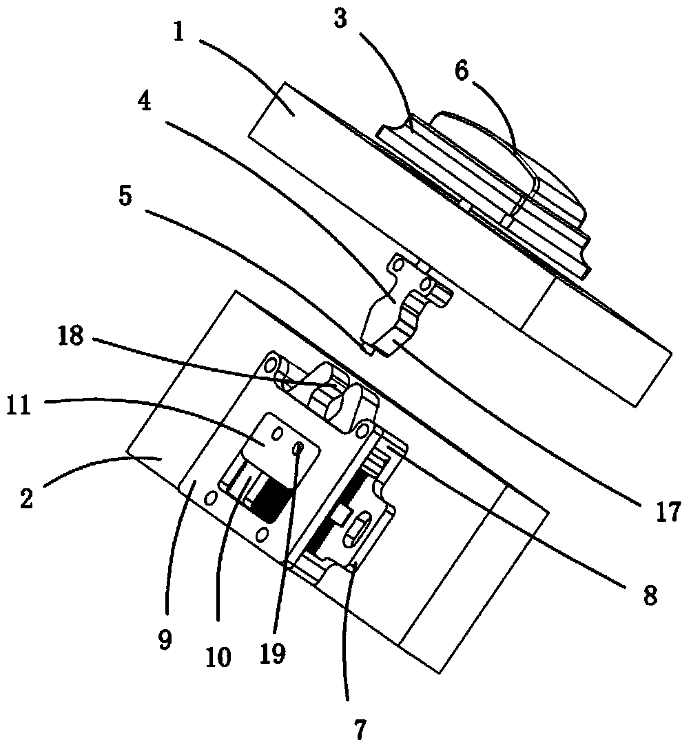
[0018] Examples, see attached figure 1 and 2 , a buckle mechanism, which includes a panel 1 and a side panel 2, the upper side of the panel is fixedly connected to a button seat 3, and the lower side of the panel is fixedly connected to a chuck 4; a guide column is movably connected to the button seat 5 button 6, and the guide post can pass through the chuck.

[0019] A base 7 is fixed on the side plate, a connecting column 8 is respectively arranged on the four feet of the base, a cover plate 9 is fixedly connected on the base, and a cavity 10 is formed between the base and the cover plate; There is a connecting piece 11, the left and right sides of the upper part of the connecting piece are respectively movably connected with the left and right button heads 12 and 13, and the lower part of the connecting piece is connected to the inner side wall of the base through a spring a14; There is a flange 15, and the flange is clamped at the connecting column on the upper part of t...


PUM


Abstract

The invention relates to a clamping mechanism. The upper side of a panel is fixed with a button seat, and the lower side is fixed with a clamping head; the button seat is connected with a button with a guide post; a side plate is fixed with a base, a cover plate is fixed to the base, and a connecting piece is arranged between the base and the cover plate; the upper part of the connecting piece is connected with a left and right gripping heads, and the lower part is connected to the base through a spring a; the left and right gripping heads are respectively provided with a flange which is clamped at the base; and the flange and the base are connected together through a spring b. When the panel moves downward to drive the clamping head, after the inclined surface of the clamping head contacts the gradient slopes on the left and right gripping heads, the left and right gripping heads are respectively opened to rotate by 14-16 degrees under the action of thrust; after the clamping head is limited by the panel, the left and right gripping heads respectively rotate back to the initial closed state to buckle the clamping head; after the button is pressed, the guide post can move downwards, so that the connecting piece moves downwards so as to drive the opened left and right gripping heads to be closed, and the clamping head can be ejected by using the closing force of the left and right gripping heads.

Description

Technical field: [0001] The invention relates to the field of buckle mechanism equipment, and more specifically relates to a buckle mechanism. Background technique: [0002] Generally, the connection between the panel and the side panel is connected by screws. The use of screws will cause inconvenience in assembly and disassembly, and the quick connection and quick separation of the panel and the side panel cannot be realized. If the screws are removed repeatedly to separate the panel from the side panel , so that the production cost is increased, and the labor intensity of the operator is also increased. Invention content: [0003] The purpose of the present invention is to provide a buckle mechanism for the deficiencies of the prior art, which can quickly connect and separate the panel and the side panel, thereby greatly improving the inconvenience of using screws to assemble and disassemble, thereby reducing the Reduce production costs and reduce the labor intensity of...

Claims


Application Information

Patent Timeline
Patent Type & Authority Applications(China)
IPC IPC(8): F16B5/00
Inventor 吕绍林杨愉强王建福段航阁
Owner BOZHON PRECISION IND TECH CO LTD
Learn More