
Transmission box cover installation method

A transmission box cover and part assembly technology, which is applied to transmission parts, belts/chains/gears, mechanical equipment, etc., can solve the problems of main shaft bearing hole stress deformation, radial runout increase, etc., to ensure the quality of part assembly , Reduce the radial runout, avoid the effect of the deformation of the spindle bearing hole

Inactive Publication Date: 2016-08-24
CHONGQING CONSTR ELECTROMECHANICAL CO LTD
View PDF5 Cites 0 Cited by
  • Summary
  • Abstract
  • Description
  • Claims
  • Application Information

AI Technical Summary

Problems solved by technology

[0004] Aiming at the technical problem in the prior art that during the installation of the engine transmission case cover, the installation of the main shaft causes the main shaft bearing hole of the transmission case cover to be deformed by force, which further increases the radial runout of the main shaft after it is press-fitted to the transmission case cover. The purpose of the invention is to provide a method for installing the cover of the engine transmission case. This method completes the partial assembly of the main shaft and the main shaft bearing through the bearing support seat, and then installs the partially assembled main shaft and the cover of the transmission case to solve the problem of pressing the main shaft to the The technical problem of the deformation of the main shaft bearing hole behind the transmission case cover

Method used


Image

  • Transmission box cover installation method
  • Transmission box cover installation method
  • Transmission box cover installation method

Examples


Embodiment Construction

[0024] The specific embodiments of the present invention will be described in further detail below in conjunction with the accompanying drawings.

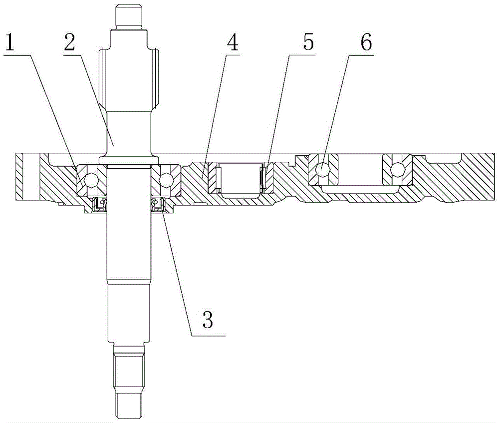
[0025] Such as figure 1 As shown, when the engine transmission case cover is installed, the main shaft bearing 1, the main shaft 2, the main shaft oil seal 3, the pinion shaft bearing 5, and the drive shaft bearing 6 need to be installed in the corresponding positions of the transmission case cover 4.

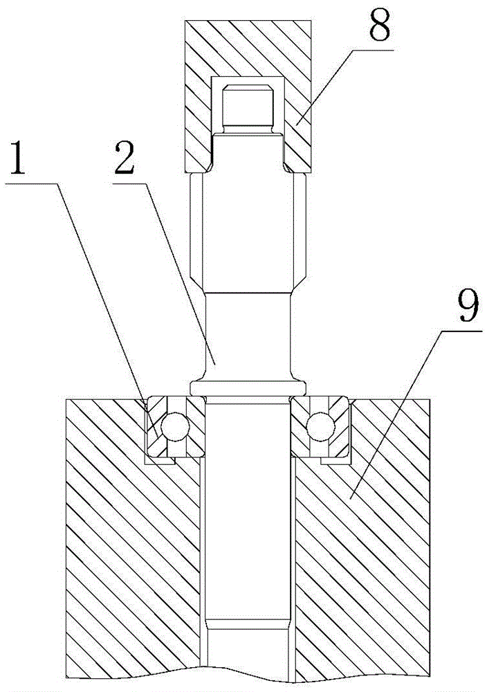
[0026] Such as image 3 with 4 As shown, the method for installing the engine gearbox cover of the present invention includes the following steps:

[0027] Step 1. Place the spindle bearing 1 on the bearing support seat 9, then put the spindle 2 into the inner hole of the spindle bearing 1, press the spindle 2 into the hole of the spindle bearing 1 through the indenter, and complete the spindle bearing 1 and the spindle 2 is installed; in this step, the indenter adopts a short indenter 8, which is convenient and flexible.

[0028] Step 2. P...


PUM


Abstract

In the transmission box cover installation method of the present invention, the main shaft and the main shaft bearing are firstly assembled through the bearing support seat, and then the partially installed main shaft is pressed into the transmission box cover, which solves the problem of first installing the main shaft bearing, and then pressing the main shaft into the transmission box cover. In the process of the transmission box cover, the technical problem of difficult alignment caused by the inclination of the main shaft; at the same time, the technical problem of deformation of the main shaft bearing hole of the transmission box cover during the alignment of the main shaft is avoided, ensuring the quality of the transmission box cover, reducing the The radial runout of the main shaft after it is press-fitted to the transmission box cover is eliminated, and the smoothness of the engine power output is ensured.

Description

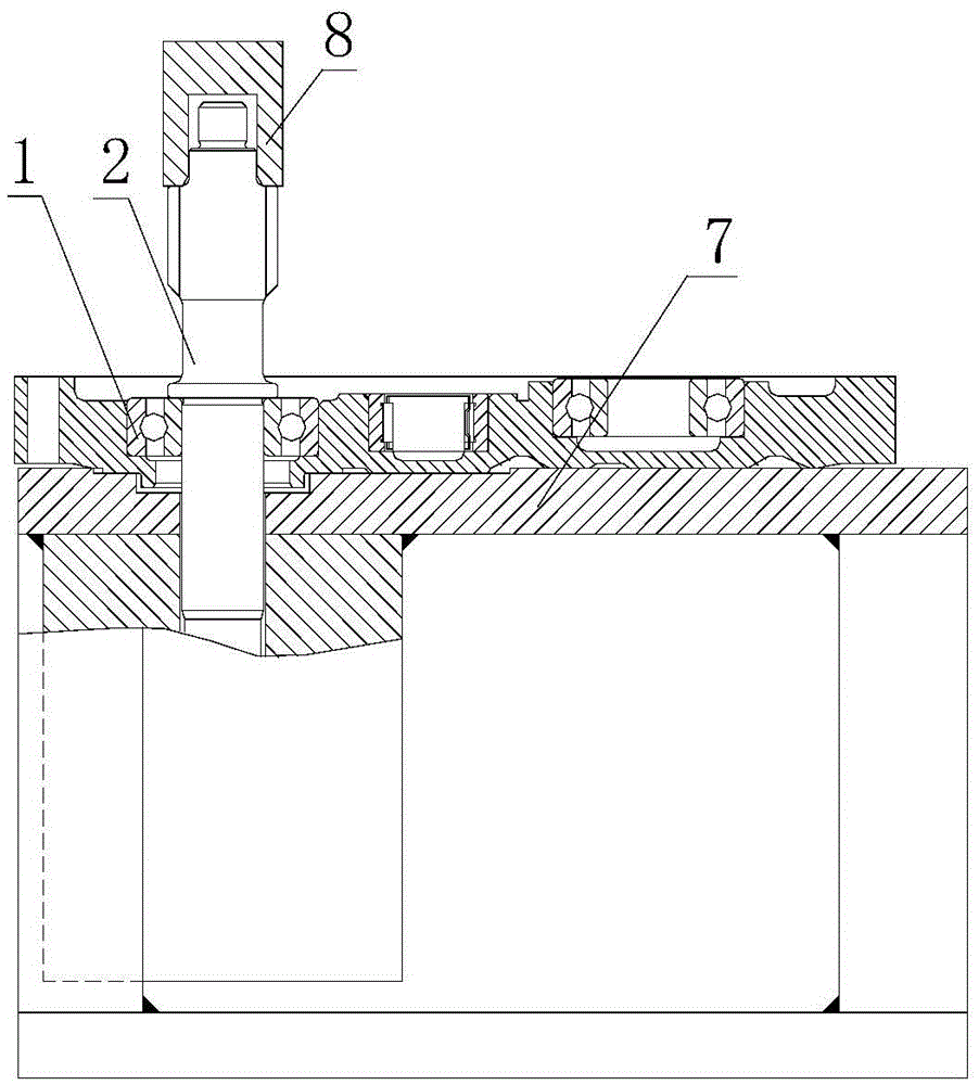
Technical field [0001] The invention relates to a method for assembling an engine transmission case cover, in particular to a method for assembling an engine transmission case cover for a scooter. Background technique [0002] Such as figure 1 with 2 As shown, at present, the method of installing the engine transmission case cover is: first place the transmission case cover 4 on the support base 7, and press the main shaft bearing 1, the wheel shaft bearing 5, and the drive shaft bearing 6 to the transmission Then press the main shaft 2 into the inner hole of the main shaft bearing 1 through the pressing head 8 at the corresponding position of the box cover 4, and press the main shaft oil seal 3 after pressing the transmission box cover installed in the flip part. [0003] When using this method to install the transmission box cover, because the length of the spindle 2 pressed into the hole of the spindle bearing 1 is long, if the spindle 2 is placed slightly inclined, the pressing...

Claims


Application Information

Patent Timeline
Patent Type & Authority Patents(China)
IPC IPC(8): F16H57/031
Inventor 陈志敏杨安芬曾凡镔
Owner CHONGQING CONSTR ELECTROMECHANICAL CO LTD
Learn More