Movable emergency power supply lighting device

A technology for lighting equipment and emergency power supply, applied in lighting and heating equipment, lighting devices, current collectors, etc., can solve the problems of fixed immobility, inability to continuously and effectively provide renewable green energy, etc., to achieve easy portability and use, and reduce weight. , the effect of high impact strength

Active Publication Date: 2013-12-25
QINGDAO SPELSBERG ELECTRICAL ENG TECH CO LTD
View PDF5 Cites 15 Cited by
  • Summary
  • Abstract
  • Description
  • Claims
  • Application Information

AI Technical Summary

Problems solved by technology

[0003] In order to solve the problems that the existing emergency power supply lighting equipment cannot continuously and effectively provide regenerative green electric energy and cannot be moved, the present invention develops a new mobile emergency power supply lighting equipment, which makes full use of solar power to generate electricity, and further integrates power generation, storage The three functional modules of electricity and power distribution are integrated into a whole that can move freely. The device can be freely carried and used in any environment, and can continuously provide green energy, ensuring the demand for electric energy and lighting in the field and in special environments.

Method used


Image

  • Movable emergency power supply lighting device
  • Movable emergency power supply lighting device

Examples


Embodiment Construction

[0018] The present invention will be further described below in conjunction with the accompanying drawings and embodiments.

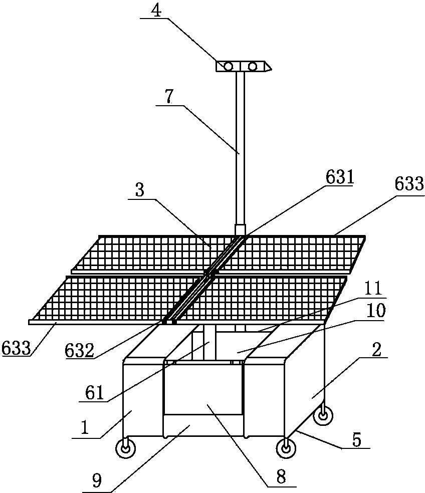
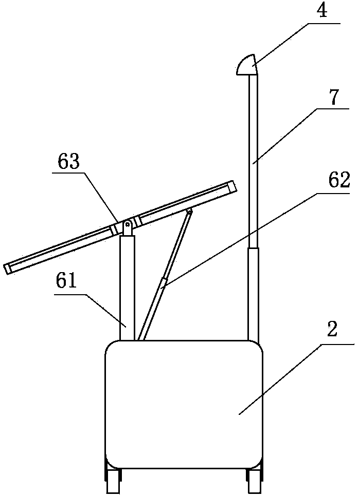
[0019] Such as figure 1 , 2 As shown, the present invention includes a power storage conversion box 1, a power distribution box 2, a solar panel 3, a lighting lamp 4, a base 5, a battery panel support, a lighting lamp lifting rod 7, and the solar battery panel 3 and the power storage conversion box 1 are electrically connected. connection, the power storage conversion box 1 is electrically connected to the power distribution box 2, and the power distribution box 2 is electrically connected to the lighting lamp 4. The power storage conversion box 1 and the power distribution box 2 are arranged on both sides of the base 5. Lifting rod 7 is arranged on the middle position of base. The base 5 is provided with four freely movable wheels.

[0020] The battery panel support includes a support lifting rod 61 , a telescopic support rod 62 , and a battery pane...


PUM


Abstract

The invention provides a movable emergency power supply lighting device which aims to solve the problems that conventional emergency power supply lighting equipment cannot continuously and effectively provide regenerative green electricity, are fixed and cannot be moved. The movable emergency power supply lighting device comprises a solar cell panel, a lighting lamp, an electricity storage conversion box, distribution boxes and a base, wherein the solar cell panel is electrically connected with the electricity storage conversion box which is electrically connected with the distribution boxes, the distribution boxes are electrically connected with the lighting lamp, and the electricity storage conversion box, the distribution boxes, the solar cell panel and the lighting lamp are arranged on the base. Furthermore, the movable emergency power supply lighting device is further provided with a cell panel support, wherein the solar cell panel is arranged on the cell panel support which can be stretched and folded freely. According to the movable emergency power supply lighting device, solar energy is fully utilized for generating electricity, and three functional modules of electricity generation, electricity storage and electricity distribution are combined into a whole which can move freely. The movable emergency power supply lighting device can be carried freely and used in any environment, continuously provide green power, and meet the requirement for the electricity and lighting in the field and special environments.

Description

technical field [0001] The invention belongs to the technical field of power supply equipment, and in particular relates to an emergency power supply lighting equipment which integrates three functional modules of power generation, power storage and power distribution into a whole and can move freely. Background technique [0002] Emergency power supply lighting equipment can continuously provide power and lighting for a period of time, so it is widely used in scientific investigations, geological exploration, and some harsh emergencies such as engineering rescue, disaster relief, field medical rescue and other fields. In the prior art, the emergency power supply lighting equipment mainly uses a field work vehicle or a storage battery to provide electric energy. However, the field operation vehicle produces a lot of noise, and the exhaust gas emitted seriously pollutes the environment and is not economical; the battery itself has limited power and low energy density, so it c...

Claims


Application Information

Patent Timeline
Patent Type & Authority Applications(China)
IPC IPC(8): H02J7/00H02J15/00H02N6/00F21S9/03
CPCY02E10/50Y02E70/30
Inventor 孙元鹏张振芳
Owner QINGDAO SPELSBERG ELECTRICAL ENG TECH CO LTD
Why Eureka
Try Eureka