Gasoline engine impeller
A gasoline engine and impeller technology, which is applied in mechanical equipment, engine components, engine cooling, etc., can solve the problems of poor power performance of the whole machine, low cooling air flow, and inability to meet the air volume required for machine cooling.
- Summary
- Abstract
- Description
- Claims
- Application Information
AI Technical Summary
Problems solved by technology
Method used
Image
Examples
Embodiment 1
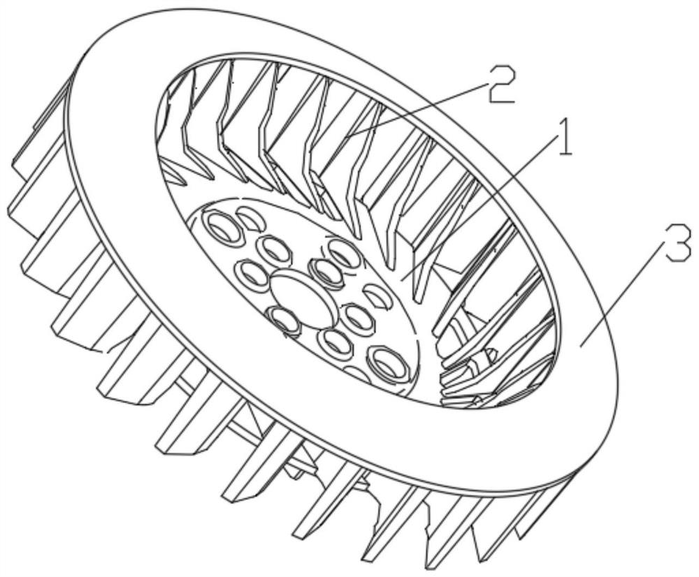
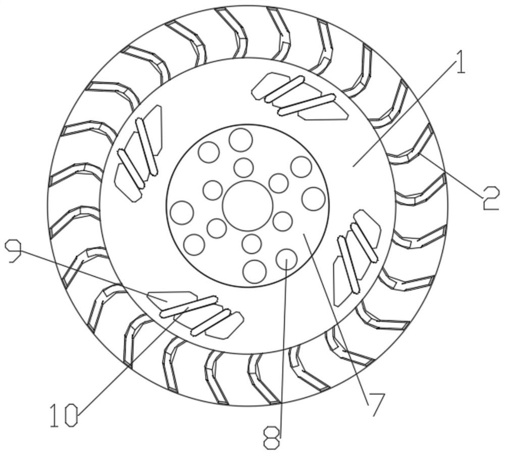
[0029] Example 1, such as Figure 1~5 As shown, the gasoline engine impeller of the present invention includes an impeller mounting base 1 and a plurality of blades 2 distributed on the edge of the end surface of the impeller mounting base 1 with the impeller mounting base 1 as the center, and a flow channel is formed between two adjacent blades 2, and the The end surface of the blade 2 away from the impeller mounting base 1 is fixed with a wind pressure ring 3, the center of the wind pressure ring 3 forms an air inlet, the wind pressure ring 3 is arranged in parallel with the impeller mounting base 1, and the wind pressure ring 3 is arranged in parallel with the impeller mounting base 1. The ring 3 is conical and its inner side is connected to the blade 2. The outer ring of the air pressure ring 3 extends outwards and has not passed the outside of the blade 2. The angle of the center of the section of the air pressure ring 3 is 130°~ 150°.
[0030] In the device of the prese...
Embodiment 2
[0031] Embodiment 2, the difference between this embodiment and Embodiment 1 is that the inner surface of the blade 2 is formed with an S-shaped inner arc segment, which is beneficial to the blade 2 to disturb the air at the air inlet when the impeller is running at high speed , so that the air at the air inlet forms a greater negative pressure swirl, thereby improving the air intake efficiency. In the present invention, the blade 2 is hook-shaped at the lower side of the air pressure ring 3, and the blade 2 extends to the inner side of the air pressure ring 3 to form a straight line, which can improve the air outlet efficiency.
[0032] Specifically, in this embodiment, the inner arc segment includes a first arc segment 4, a second arc segment 5 and a third arc segment 6, and the arc direction of the second arc segment 5 is the same as that of the first arc segment. The arc directions of the circular arc segment 4 and the third circular arc segment 6 are opposite, and the fir...
Embodiment 3
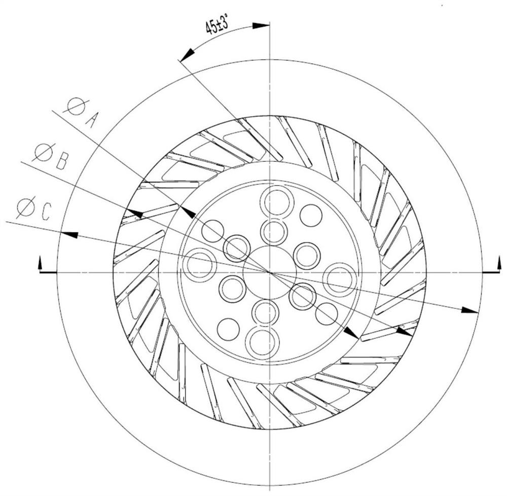
[0033] Embodiment 3. The difference between this embodiment and Embodiment 2 is that in this embodiment, the relative inclination angle between the blade 2 and the radial direction of the circumference is 45±3°, and the inclination angle of the blade 2 directly affects the negative pressure of the air intake. The design angle is 45±3°, which is the best angle through CAE analysis and test verification. Compared with ordinary impellers, the air intake can be increased by 5%.
[0034] In this embodiment, the center of the impeller mounting seat 1 is provided with an impeller seat 7, and several installation holes 8 are opened on the impeller seat 7.
[0035] In this embodiment, several groups of heat dissipation holes 9 are opened on the impeller mounting base 1, and through holes 10 are formed between two adjacent heat dissipation holes 9, and the blades 2 located at the through holes 10 extend out of the through holes. After 10, it extends outward, which can be used for heat d...
PUM
 Abstract
Description
Claims
Application Information
 - R&D
- Intellectual Property
- Life Sciences
- Materials
- Tech Scout
- Unparalleled Data Quality
- Higher Quality Content
- 60% Fewer Hallucinations
Browse by: Latest US Patents, China's latest patents, Technical Efficacy Thesaurus, Application Domain, Technology Topic, Popular Technical Reports.
© 2025 PatSnap. All rights reserved.Legal|Privacy policy|Modern Slavery Act Transparency Statement|Sitemap|About US| Contact US: help@patsnap.com


